

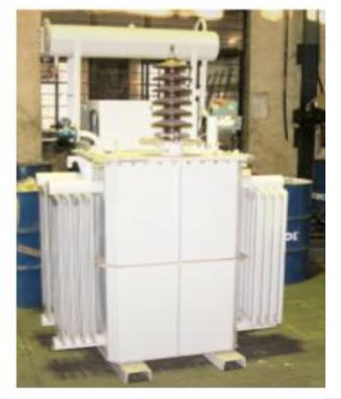
TR &TRCC-1Φ
Explore Our Products
-
110KVP/
100mA -
110KVP/
150mA -
110KVP/
200mA -
110KVP/
250mA -
110KVP/
300mA -
110KVP/
400mA -
110KVP/
500mA -
110KVP/
600mA -
110KVP/
700mA -
110KVP/
800mA -
110KVP/
900mA -
110KVP/
1100mA
Rapper control system is designed specifically for ESP application. This rapper control system is designed to be used with electrical solenoid type impact rappers. These rappers are also called as magnetic impulse gravity impact (MIGI) rappers. Field installed RDB panel has provided with special type of diode.
- PLC based rapper systems
- 7″ Touchscreen HMI for operation.
- Matrix type & Non matrix type configuration
- Open communication protocol interface with plant DCS systems.
- Easy maintenance
- Suitable for ESP application in industries like Sugar plant, Cement plant, steel plant, Power plant, etc.
| RECTIFIER/ TR SET | 110KVP/100mA |
| Make | Autodata |
| Type | TR-110/100 |
| Power | 10.2 kVA |
| Rated Primary Voltage | 415 V |
| Suitable for Voltage variation | ±10% |
| Rated primary Current | 25 Amps |
| Rated Frequency | 50 Hz |
| Suitable for Frequency variation | ± 5% |
| No of phases primary | 2-ph |
| Output Voltage | 110kVP DC at no load |
| Output Current | 100 mA |
| Output Power | 7 kW |
| Efficiency | 88% |
| No. of Primary taps supplied | Nil |
| Tap Voltage | Not applicable |
| 1 minute power frequency withstand voltage | 3 kV |
| Impulse withstand voltage | 250 kVP (Only for transformer) |
| % of impedance system | 33 % ±10% |
| Enclosure protection | IP 55 |
| Transformation Ratio | 189.2 |
| Form factor | Voltage – 1.1,Current – 1.3 |
| Type of Cooling | ONAN |
| Type of Oil | Mineral Oil as per IS:335 |
| Total oil requirement (approx.) | 260litres |
| Dielectric strength of oil (with 2.5mm) | 60 kV |
| Flash Point of oil | >140°C |
| Type of oil level gauge | Sight Glass |
| No Load losses at expected operating voltage | 600 W (Subject to IS tolerance) |
| Load losses (Short Circuit) | 250 W (Subject to IS tolerance) |
| Miscellaneous losses if any | 150 W |
| Class of Insulation | Class A |
| TR Unit construction | Hermetically sealed without conservator without breather |
| HT Bushing orientation | Horizontal |
| Earthing Switch | Inbuilt |
| Class of insulating winding | |
| (I) L.V. | Class A |
| (II) H.V. | Class B |
| Range of Oil Temperature Indicator | 0° C – 120° C |
| Class of L.V. bushing | 1.1 kV Class |
| Class of H.V bushing | Suitable for 110kVP DC |
| Creepage distance of HV Bushing | Min. 840 mm |
| Paint Shade | RAL 7032, Siemens Grey |
| Painting thickness in microns | > 60 microns |
| List of TR set Protection | Pressure Release Valve |
| Oil Temp. Indicator – I – Alarm | |
| Oil Temp. Indicator – II – Trip | |
| Pressure High – Trip | |
| Low Oil Level – Trip | |
| TR set Grounded – Trip | |
| Rectifier | |
| Type | Full Wave Bridge |
| Make | Autodata |
| Diode type | Avalanche Diode |
| Rating | 7 kW |
| Half wave/full wave rectification | Full wave rectification |
| Rated current output of each rectifier set | 100 mA |
| Rated voltage output of each rectifier set | 110 kV Peak at no load |
| Peak inverse voltage of diode bridge | 226 kV |
| No of Earthing terminal | 2 |
| TR Control Panel | |
| Make | Autodata |
| Type | TRCC 110/100 |
| Rated voltage output | 415 V |
| Rated Current output | 25 Amps |
| Rated frequency | 50 Hz |
| Heat dissipation of panel | 200 W |
| Panel enclosure protection | IP 42 |
| Suitable for Voltage variation | ±10% |
| Suitable for Frequency variation | ±5% |
| Thyristor rating | Min. 55A |
| Type of over voltage protector | G. D. Tube |
| No. Of Earthing terminal | 2 |
| Paint Shade | RAL 7032, Siemens Grey |
| Painting thickness in microns | >50 microns |
| Controller | Calculus |
Rapper control system is designed specifically for ESP application. This rapper control system is designed to be used with electrical solenoid type impact rappers. These rappers are also called as magnetic impulse gravity impact (MIGI) rappers. Field installed RDB panel has provided with special type of diode.
- PLC based rapper systems
- 7″ Touchscreen HMI for operation.
- Matrix type & Non matrix type configuration
- Open communication protocol interface with plant DCS systems.
- Easy maintenance
- Suitable for ESP application in industries like Sugar plant, Cement plant, steel plant, Power plant, etc.
| 1.0 RECTIFIER/ TR SET | 110KVP/150mA |
| 1.1 Make | Autodata |
| 1.2 Type | TR-110/150 |
| 1.3 Power | 15.3 kVA |
| 1.4 Rated Primary Voltage | 415 V |
| 1.5 Suitable for Voltage variation | ±10% |
| 1.6 Rated primary Current | 37 Amps |
| 1.7 Rated Frequency | 50 Hz |
| 1.8 Suitable for Frequency variation | ± 5% |
| 1.9 No of phases primary | 2-ph |
| 1.10 Output Voltage | 110 kVP DC at no load |
| 1.11 Output Current | 150 mA |
| 1.12 Output Power | 10.5 kW |
| 1.13 Efficiency | 89% |
| 1.14 No. of Primary taps supplied | Nil |
| 1.15 Tap Voltage | Not applicable |
| 1.16 1 minute power frequency withstand voltage | 3 kV |
| 1.17 Impulse withstand voltage | 250 kVP (Only for transformer) |
| 1.18 % of impedance system | 33 % ±10% |
| 1.19 Enclosure protection | IP 55 |
| 1.20 Transformation Ratio | 189.2 |
| 1.21 Form factor | Voltage – 1.1,Current – 1.3 |
| 1.22 Type of Cooling | ONAN |
| 1.23 Type of Oil | Mineral Oil as per IS:335 |
| 1.24 Total oil requirement (approx.) | 260litres |
| 1.25 Dielectric strength of oil (with 2.5mm) | 60 kV |
| 1.26 Flash Point of oil | >140°C |
| 1.27 Type of oil level gauge | Sight Glass |
| 1.28 No Load losses at expected operating voltage | 600 W (Subject to IS tolerance) |
| 1.29 Load losses (Short Circuit) | 400 W (Subject to IS tolerance) |
| 1.30 Miscellaneous losses if any | 250 W |
| 1.31 Class of Insulation | Class A |
| 1.32 TR Unit construction | Hermetically sealed without conservator without breather |
| 1.33 HT Bushing orientation | Horizontal |
| 1.34 Earthing Switch | Inbuilt |
| 1.35 Class of insulating winding | |
| (I) L.V. | Class A |
| (II) H.V. | Class B |
| 1.36 Range of Oil Temperature Indicator | 0° C – 120° C |
| 1.37 Class of L.V. bushing | 1.1 kV Class |
| 1.38 Class of H.V bushing | Suitable for 110 kVP DC |
| 1.39 Creepage distance of HV Bushing | Min. 840 mm |
| 1.40 Paint Shade | RAL 7032, Siemens Grey |
| 1.41 Painting thickness in microns | > 60 microns |
| 1.42 List of TR set Protection | Pressure Release Valve |
| Oil Temp. Indicator – I – Alarm | |
| Oil Temp. Indicator – II – Trip | |
| Pressure High – Trip | |
| Low Oil Level – Trip | |
| TR set Grounded – Trip | |
| 2.0 Rectifier | |
| 2.1 Type | Full Wave Bridge |
| 2.2 Make | Autodata |
| 2.3 Diode type | Avalanche Diode |
| 2.4 Rating | 10.5 kW |
| 2.5 Half wave/full wave rectification | Full wave rectification |
| 2.6 Rated current output of each rectifier set | 150 mA |
| 2.7 Rated voltage output of each rectifier set | 110 kV Peak at no load |
| 2.8 Peak inverse voltage of diode bridge | 226 kV |
| 2.9 No of Earthing terminal | 2 |
| 3.0 TR Control Panel | |
| 3.1 Make | Autodata |
| 3.2 Type | TRCC 110/150 |
| 3.3 Rated voltage output | 415 V |
| 3.4 Rated Current output | 37 Amps |
| 3.5 Rated frequency | 50 Hz |
| 3.6 Heat dissipation of panel | 250 W |
| 3.7 Panel enclosure protection | IP 42 |
| 3.8 Suitable for Voltage variation | ±10% |
| 3.9 Suitable for Frequency variation | ±5% |
| 3.10 Thyristor rating | Min. 55A |
| 3.11 Type of over voltage protector | G. D. Tube |
| 3.12 No. Of Earthing terminal | 2 |
| 3.13 Paint Shade | RAL 7032, Siemens Grey |
| 3.14 Painting thickness in microns | >50 microns |
| 3.15 Controller | Calculus |
Rapper control system is designed specifically for ESP application. This rapper control system is designed to be used with electrical solenoid type impact rappers. These rappers are also called as magnetic impulse gravity impact (MIGI) rappers. Field installed RDB panel has provided with special type of diode.
- PLC based rapper systems
- 7″ Touchscreen HMI for operation.
- Matrix type & Non matrix type configuration
- Open communication protocol interface with plant DCS systems.
- Easy maintenance
- Suitable for ESP application in industries like Sugar plant, Cement plant, steel plant, Power plant, etc.
| 1.0 RECTIFIER/ TR SET | 110KVP/200mA |
| 1.1 Make | Autodata |
| 1.2 Type | TR-110/200 |
| 1.3 Power | 20.4 kVA |
| 1.4 Rated Primary Voltage | 415 V |
| 1.5 Suitable for Voltage variation | ±10% |
| 1.6 Rated primary Current | 49 Amps |
| 1.7 Rated Frequency | 50 Hz |
| 1.8 Suitable for Frequency variation | ± 5% |
| 1.9 No of phases primary | 2-ph |
| 1.10 Output Voltage | 110 kVP DC at no load |
| 1.11 Output Current | 200 mA |
| 1.12 Output Power | 14 kW |
| 1.13 Efficiency | 90% |
| 1.14 No. of Primary taps supplied | Nil |
| 1.15 Tap Voltage | Not applicable |
| 1.16 1 minute power frequency withstand voltage | 3 kV |
| 1.17 Impulse withstand voltage | 250 kVP (Only for transformer) |
| 1.18 % of impedance system | 33 % ±10% |
| 1.19 Enclosure protection | IP 55 |
| 1.20 Transformation Ratio | 189.2 |
| 1.21 Form factor | Voltage – 1.1,Current – 1.3 |
| 1.22 Type of Cooling | ONAN |
| 1.23 Type of Oil | Mineral Oil as per IS:335 |
| 1.24 Total oil requirement (approx.) | 260litres |
| 1.25 Dielectric strength of oil (with 2.5mm) | 60 kV |
| 1.26 Flash Point of oil | >140°C |
| 1.27 Type of oil level gauge | Sight Glass |
| 1.28 No Load losses at expected operating voltage | 600 W (Subject to IS tolerance) |
| 1.29 Load losses (Short Circuit) | 600 W (Subject to IS tolerance) |
| 1.30 Miscellaneous losses if any | 400 W |
| 1.31 Class of Insulation | Class A |
| 1.32 TR Unit construction | Hermetically sealed without conservator without breather |
| 1.33 HT Bushing orientation | Horizontal |
| 1.34 Earthing Switch | Inbuilt |
| 1.35 Class of insulating winding | |
| (I) L.V. | Class A |
| (II) H.V. | Class B |
| 1.36 Range of Oil Temperature Indicator | 0° C – 120° C |
| 1.37 Class of L.V. bushing | 1.1 kV Class |
| 1.38 Class of H.V bushing | Suitable for 110 kVP DC |
| 1.39 Creepage distance of HV Bushing | Min. 840 mm |
| 1.40 Paint Shade | RAL 7032, Siemens Grey |
| 1.41 Painting thickness in microns | > 60 microns |
| 1.42 List of TR set Protection | Pressure Release Valve |
| Oil Temp. Indicator – I – Alarm | |
| Oil Temp. Indicator – II – Trip | |
| Pressure High – Trip | |
| Low Oil Level – Trip | |
| TR set Grounded – Trip | |
| 2.0 Rectifier | |
| 2.1 Type | Full Wave Bridge |
| 2.2 Make | Autodata |
| 2.3 Diode type | Avalanche Diode |
| 2.4 Rating | 14 kW |
| 2.5 Half wave/full wave rectification | Full wave rectification |
| 2.6 Rated current output of each rectifier set | 200 mA |
| 2.7 Rated voltage output of each rectifier set | 110 kV Peak at no load |
| 2.8 Peak inverse voltage of diode bridge | 226 kV |
| 2.9 No of Earthing terminal | 2 |
| 3.0 TR Control Panel | |
| 3.1 Make | Autodata |
| 3.2 Type | TRCC 110/200 |
| 3.3 Rated voltage output | 415 V |
| 3.4 Rated Current output | 49 Amps |
| 3.5 Rated frequency | 50 Hz |
| 3.6 Heat dissipation of panel | 300 W |
| 3.7 Panel enclosure protection | IP 42 |
| 3.8 Suitable for Voltage variation | ±10% |
| 3.9 Suitable for Frequency variation | ±5% |
| 3.10 Thyristor rating | Min. 90A |
| 3.11 Type of over voltage protector | G. D. Tube |
| 3.12 No. Of Earthing terminal | 2 |
| 3.13 Paint Shade | RAL 7032, Siemens Grey |
| 3.14 Painting thickness in microns | >50 microns |
| 3.15 Controller | Calculus |
Rapper control system is designed specifically for ESP application. This rapper control system is designed to be used with electrical solenoid type impact rappers. These rappers are also called as magnetic impulse gravity impact (MIGI) rappers. Field installed RDB panel has provided with special type of diode.
- PLC based rapper systems
- 7″ Touchscreen HMI for operation.
- Matrix type & Non matrix type configuration
- Open communication protocol interface with plant DCS systems.
- Easy maintenance
- Suitable for ESP application in industries like Sugar plant, Cement plant, steel plant, Power plant, etc.
| 1.0 RECTIFIER/ TR SET | 110KVP/250mA |
| 1.1 Make | Autodata |
| 1.2 Type | TR-110/250 |
| 1.3 Power | 25.5 kVA |
| 1.4 Rated Primary Voltage | 415 V |
| 1.5 Suitable for Voltage variation | ±10% |
| 1.6 Rated primary Current | 62 Amps |
| 1.7 Rated Frequency | 50 Hz |
| 1.8 Suitable for Frequency variation | ± 5% |
| 1.9 No of phases primary | 2-ph |
| 1.10 Output Voltage | 110 kVP DC at no load |
| 1.11 Output Current | 250 mA |
| 1.12 Output Power | 17.5 kW |
| 1.13 Efficiency | 90% |
| 1.14 No. of Primary taps supplied | Nil |
| 1.15 Tap Voltage | Not applicable |
| 1.16 1 minute power frequency withstand voltage | 3 kV |
| 1.17 Impulse withstand voltage | 250 kVP (Only for transformer) |
| 1.18 % of impedance system | 33 % ±10% |
| 1.19 Enclosure protection | IP 55 |
| 1.20 Transformation Ratio | 189.2 |
| 1.21 Form factor | Voltage – 1.1,Current – 1.3 |
| 1.22 Type of Cooling | ONAN |
| 1.23 Type of Oil | Mineral Oil as per IS:335 |
| 1.24 Total oil requirement (approx.) | 260litres |
| 1.25 Dielectric strength of oil (with 2.5mm) | 60 kV |
| 1.26 Flash Point of oil | >140°C |
| 1.27 Type of oil level gauge | Sight Glass |
| 1.28 No Load losses at expected operating voltage | 600 W (Subject to IS tolerance) |
| 1.29 Load losses (Short Circuit) | 800 W (Subject to IS tolerance) |
| 1.30 Miscellaneous losses if any | 500 W |
| 1.31 Class of Insulation | Class A |
| 1.32 TR Unit construction | Hermetically sealed without conservator without breather |
| 1.33 HT Bushing orientation | Horizontal |
| 1.34 Earthing Switch | Inbuilt |
| 1.35 Class of insulating winding | |
| (I) L.V. | Class A |
| (II) H.V. | Class B |
| 1.36 Range of Oil Temperature Indicator | 0° C – 120° C |
| 1.37 Class of L.V. bushing | 1.1 kV Class |
| 1.38 Class of H.V bushing | Suitable for 110 kVP DC |
| 1.39 Creepage distance of HV Bushing | Min. 840 mm |
| 1.40 Paint Shade | RAL 7032, Siemens Grey |
| 1.41 Painting thickness in microns | > 60 microns |
| 1.42 List of TR set Protection | Pressure Release Valve |
| Oil Temp. Indicator – I – Alarm | |
| Oil Temp. Indicator – II – Trip | |
| Pressure High – Trip | |
| Low Oil Level – Trip | |
| TR set Grounded – Trip | |
| 2.0 Rectifier | |
| 2.1 Type | Full Wave Bridge |
| 2.2 Make | Autodata |
| 2.3 Diode type | Avalanche Diode |
| 2.4 Rating | 17.5 kW |
| 2.5 Half wave/full wave rectification | Full wave rectification |
| 2.6 Rated current output of each rectifier set | 250 mA |
| 2.7 Rated voltage output of each rectifier set | 110 kV Peak at no load |
| 2.8 Peak inverse voltage of diode bridge | 226 kV |
| 2.9 No of Earthing terminal | 2 |
| 3.0 TR Control Panel | |
| 3.1 Make | Autodata |
| 3.2 Type | TRCC 110/250 |
| 3.3 Rated voltage output | 415 V |
| 3.4 Rated Current output | 62 Amps |
| 3.5 Rated frequency | 50 Hz |
| 3.6 Heat dissipation of panel | 300 W |
| 3.7 Panel enclosure protection | IP 42 |
| 3.8 Suitable for Voltage variation | ±10% |
| 3.9 Suitable for Frequency variation | ±5% |
| 3.10 Thyristor rating | Min. 90A |
| 3.11 Type of over voltage protector | G. D. Tube |
| 3.12 No. Of Earthing terminal | 2 |
| 3.13 Paint Shade | RAL 7032, Siemens Grey |
| 3.14 Painting thickness in microns | >50 microns |
| 3.15 Controller | Calculus |
Rapper control system is designed specifically for ESP application. This rapper control system is designed to be used with electrical solenoid type impact rappers. These rappers are also called as magnetic impulse gravity impact (MIGI) rappers. Field installed RDB panel has provided with special type of diode.
- PLC based rapper systems
- 7″ Touchscreen HMI for operation.
- Matrix type & Non matrix type configuration
- Open communication protocol interface with plant DCS systems.
- Easy maintenance
- Suitable for ESP application in industries like Sugar plant, Cement plant, steel plant, Power plant, etc.
| 1.0 RECTIFIER/ TR SET | 110KVP/300mA |
| 1.1 Make | Autodata |
| 1.2 Type | TR-110/300 |
| 1.3 Power | 30.6 kVA |
| 1.4 Rated Primary Voltage | 415 V |
| 1.5 Suitable for Voltage variation | ±10% |
| 1.6 Rated primary Current | 74 Amps |
| 1.7 Rated Frequency | 50 Hz |
| 1.8 Suitable for Frequency variation | ± 5% |
| 1.9 No of phases primary | 2-ph |
| 1.10 Output Voltage | 110kVP DC at no load |
| 1.11 Output Current | 300 mA |
| 1.12 Output Power | 21 kW |
| 1.13 Efficiency | 90% |
| 1.14 No. of Primary taps supplied | Nil |
| 1.15 Tap Voltage | Not applicable |
| 1.16 1 minute power frequency withstand voltage | 3 kV |
| 1.17 Impulse withstand voltage | 250 kVP (Only for transformer) |
| 1.18 % of impedance system | 33 % ±10% |
| 1.19 Enclosure protection | IP 55 |
| 1.20 Transformation Ratio | 189.2 |
| 1.21 Form factor | Voltage – 1.1,Current – 1.3 |
| 1.22 Type of Cooling | ONAN |
| 1.23 Type of Oil | Mineral Oil as per IS:335 |
| 1.24 Total oil requirement (approx.) | 260litres |
| 1.25 Dielectric strength of oil (with 2.5mm) | 60 kV |
| 1.26 Flash Point of oil | >140°C |
| 1.27 Type of oil level gauge | Sight Glass |
| 1.28 No Load losses at expected operating voltage | 600 W (Subject to IS tolerance) |
| 1.29 Load losses (Short Circuit) | 1000 W (Subject to IS tolerance) |
| 1.30 Miscellaneous losses if any | 600 W |
| 1.31 Class of Insulation | Class A |
| 1.32 TR Unit construction | Hermetically sealed without conservator without breather |
| 1.33 HT Bushing orientation | Horizontal |
| 1.34 Earthing Switch | Inbuilt |
| 1.35 Class of insulating winding | |
| (I) L.V. | Class A |
| (II) H.V. | Class B |
| 1.36 Range of Oil Temperature Indicator | 0° C – 120° C |
| 1.37 Class of L.V. bushing | 1.1 kV Class |
| 1.38 Class of H.V bushing | Suitable for 110kVP DC |
| 1.39 Creepage distance of HV Bushing | Min. 840 mm |
| 1.40 Paint Shade | RAL 7032, Siemens Grey |
| 1.41 Painting thickness in microns | > 60 microns |
| 1.42 List of TR set Protection | Pressure Release Valve |
| Oil Temp. Indicator – I – Alarm | |
| Oil Temp. Indicator – II – Trip | |
| Pressure High – Trip | |
| Low Oil Level – Trip | |
| TR set Grounded – Trip | |
| 2.0 Rectifier | |
| 2.1 Type | Full Wave Bridge |
| 2.2 Make | Autodata |
| 2.3 Diode type | Avalanche Diode |
| 2.4 Rating | 21 kW |
| 2.5 Half wave/full wave rectification | Full wave rectification |
| 2.6 Rated current output of each rectifier set | 300 mA |
| 2.7 Rated voltage output of each rectifier set | 110 kV Peak at no load |
| 2.8 Peak inverse voltage of diode bridge | 226 kV |
| 2.9 No of Earthing terminal | 2 |
| 3.0 TR Control Panel | |
| 3.1 Make | Autodata |
| 3.2 Type | TRCC 110/300 |
| 3.3 Rated voltage output | 415 V |
| 3.4 Rated Current output | 74 Amps |
| 3.5 Rated frequency | 50 Hz |
| 3.6 Heat dissipation of panel | 400 W |
| 3.7 Panel enclosure protection | IP 42 |
| 3.8 Suitable for Voltage variation | ±10% |
| 3.9 Suitable for Frequency variation | ±5% |
| 3.10 Thyristor rating | Min. 110A |
| 3.11 Type of over voltage protector | G. D. Tube |
| 3.12 No. Of Earthing terminal | 2 |
| 3.13 Paint Shade | RAL 7032, Siemens Grey |
| 3.14 Painting thickness in microns | >50 microns |
| 3.15 Controller | Calculus |
Rapper control system is designed specifically for ESP application. This rapper control system is designed to be used with electrical solenoid type impact rappers. These rappers are also called as magnetic impulse gravity impact (MIGI) rappers. Field installed RDB panel has provided with special type of diode.
- PLC based rapper systems
- 7″ Touchscreen HMI for operation.
- Matrix type & Non matrix type configuration
- Open communication protocol interface with plant DCS systems.
- Easy maintenance
- Suitable for ESP application in industries like Sugar plant, Cement plant, steel plant, Power plant, etc.
| 1.0 RECTIFIER/ TR SET | 110KVP/400mA |
| 1.1 Make | Autodata |
| 1.2 Type | TR-110/400 |
| 1.3 Power | 40.8 kVA |
| 1.4 Rated Primary Voltage | 415 V |
| 1.5 Suitable for Voltage variation | ±10% |
| 1.6 Rated primary Current | 98 Amps |
| 1.7 Rated Frequency | 50 Hz |
| 1.8 Suitable for Frequency variation | ± 5% |
| 1.9 No of phases primary | 2-ph |
| 1.10 Output Voltage | 110 kVP DC at no load |
| 1.11 Output Current | 400 mA |
| 1.12 Output Power | 28 kW |
| 1.13 Efficiency | 91% |
| 1.14 No. of Primary taps supplied | Nil |
| 1.15 Tap Voltage | Not applicable |
| 1.16 1 minute power frequency withstand voltage | 3 kV |
| 1.17 Impulse withstand voltage | 250 kVP (Only for transformer) |
| 1.18 % of impedance system | 33 % ±10% |
| 1.19 Enclosure protection | IP 55 |
| 1.20 Transformation Ratio | 189.2 |
| 1.21 Form factor | Voltage – 1.1,Current – 1.3 |
| 1.22 Type of Cooling | ONAN |
| 1.23 Type of Oil | Mineral Oil as per IS:335 |
| 1.24 Total oil requirement (approx.) | 260litres |
| 1.25 Dielectric strength of oil (with 2.5mm) | 60 kV |
| 1.26 Flash Point of oil | >140°C |
| 1.27 Type of oil level gauge | Sight Glass |
| 1.28 No Load losses at expected operating voltage | 600 W (Subject to IS tolerance) |
| 1.29 Load losses (Short Circuit) | 1200 W (Subject to IS tolerance) |
| 1.30 Miscellaneous losses if any | 700 W |
| 1.31 Class of Insulation | Class A |
| 1.32 TR Unit construction | Hermetically sealed without conservator without breather |
| 1.33 HT Bushing orientation | Horizontal |
| 1.34 Earthing Switch | Inbuilt |
| 1.35 Class of insulating winding | |
| (I) L.V. | Class A |
| (II) H.V. | Class B |
| 1.36 Range of Oil Temperature Indicator | 0° C – 120° C |
| 1.37 Class of L.V. bushing | 1.1 kV Class |
| 1.38 Class of H.V bushing | Suitable for 110 kVP DC |
| 1.39 Creepage distance of HV Bushing | Min. 840 mm |
| 1.40 Paint Shade | RAL 7032, Siemens Grey |
| 1.41 Painting thickness in microns | > 60 microns |
| 1.42 List of TR set Protection | Pressure Release Valve |
| Oil Temp. Indicator – I – Alarm | |
| Oil Temp. Indicator – II – Trip | |
| Pressure High – Trip | |
| Low Oil Level – Trip | |
| TR set Grounded – Trip | |
| 2.0 Rectifier | |
| 2.1 Type | Full Wave Bridge |
| 2.2 Make | Autodata |
| 2.3 Diode type | Avalanche Diode |
| 2.4 Rating | 28 kW |
| 2.5 Half wave/full wave rectification | Full wave rectification |
| 2.6 Rated current output of each rectifier set | 400 mA |
| 2.7 Rated voltage output of each rectifier set | 110 kV Peak at no load |
| 2.8 Peak inverse voltage of diode bridge | 226 kV |
| 2.9 No of Earthing terminal | 2 |
| 3.0 TR Control Panel | |
| 3.1 Make | Autodata |
| 3.2 Type | TRCC 110/400 |
| 3.3 Rated voltage output | 415 V |
| 3.4 Rated Current output | 98 Amps |
| 3.5 Rated frequency | 50 Hz |
| 3.6 Heat dissipation of panel | 500 W |
| 3.7 Panel enclosure protection | IP 42 |
| 3.8 Suitable for Voltage variation | ±10% |
| 3.9 Suitable for Frequency variation | ±5% |
| 3.10 Thyristor rating | Min. 160A |
| 3.11 Type of over voltage protector | G. D. Tube |
| 3.12 No. Of Earthing terminal | 2 |
| 3.13 Paint Shade | RAL 7032, Siemens Grey |
| 3.14 Painting thickness in microns | >50 microns |
| 3.15 Controller | Calculus |
Rapper control system is designed specifically for ESP application. This rapper control system is designed to be used with electrical solenoid type impact rappers. These rappers are also called as magnetic impulse gravity impact (MIGI) rappers. Field installed RDB panel has provided with special type of diode.
- PLC based rapper systems
- 7″ Touchscreen HMI for operation.
- Matrix type & Non matrix type configuration
- Open communication protocol interface with plant DCS systems.
- Easy maintenance
- Suitable for ESP application in industries like Sugar plant, Cement plant, steel plant, Power plant, etc.
| 1.0 RECTIFIER/ TR SET | 110KVP/500mA |
| 1.1 Make | Autodata |
| 1.2 Type | TR-110/500 |
| 1.3 Power | 51 kVA |
| 1.4 Rated Primary Voltage | 415 V |
| 1.5 Suitable for Voltage variation | ±10% |
| 1.6 Rated primary Current | 123 Amps |
| 1.7 Rated Frequency | 50 Hz |
| 1.8 Suitable for Frequency variation | ± 5% |
| 1.9 No of phases primary | 2-ph |
| 1.10 Output Voltage | 110 kVP DC at no load |
| 1.11 Output Current | 500 mA |
| 1.12 Output Power | 35 kW |
| 1.13 Efficiency | 91% |
| 1.14 No. of Primary taps supplied | Nil |
| 1.15 Tap Voltage | Not applicable |
| 1.16 1 minute power frequency withstand voltage | 3 kV |
| 1.17 Impulse withstand voltage | 250 kVP (Only for transformer) |
| 1.18 % of impedance system | 33 % ±10% |
| 1.19 Enclosure protection | IP 55 |
| 1.20 Transformation Ratio | 189.2 |
| 1.21 Form factor | Voltage – 1.1,Current – 1.3 |
| 1.22 Type of Cooling | ONAN |
| 1.23 Type of Oil | Mineral Oil as per IS:335 |
| 1.24 Total oil requirement (approx.) | 440litres |
| 1.25 Dielectric strength of oil (with 2.5mm) | 60 kV |
| 1.26 Flash Point of oil | >140°C |
| 1.27 Type of oil level gauge | Sight Glass |
| 1.28 No Load losses at expected operating voltage | 750 W (Subject to IS tolerance) |
| 1.29 Load losses (Short Circuit) | 2000 W (Subject to IS tolerance) |
| 1.30 Miscellaneous losses if any | 550 W |
| 1.31 Class of Insulation | Class A |
| 1.32 TR Unit construction | Hermetically sealed without conservator without breather |
| 1.33 HT Bushing orientation | Horizontal |
| 1.34 Earthing Switch | Inbuilt |
| 1.35 Class of insulating winding | |
| (I) L.V. | Class A |
| (II) H.V. | Class B |
| 1.36 Range of Oil Temperature Indicator | 0° C – 120° C |
| 1.37 Class of L.V. bushing | 1.1 kV Class |
| 1.38 Class of H.V bushing | Suitable for 110 kVP DC |
| 1.39 Creepage distance of HV Bushing | Min. 840 mm |
| 1.40 Paint Shade | RAL 7032, Siemens Grey |
| 1.41 Painting thickness in microns | > 60 microns |
| 1.42 List of TR set Protection | Pressure Release Valve |
| Oil Temp. Indicator – I – Alarm | |
| Oil Temp. Indicator – II – Trip | |
| Pressure High – Trip | |
| Low Oil Level – Trip | |
| TR set Grounded – Trip | |
| 2.0 Rectifier | |
| 2.1 Type | Full Wave Bridge |
| 2.2 Make | Autodata |
| 2.3 Diode type | Avalanche Diode |
| 2.4 Rating | 35 kW |
| 2.5 Half wave/full wave rectification | Full wave rectification |
| 2.6 Rated current output of each rectifier set | 500 mA |
| 2.7 Rated voltage output of each rectifier set | 110 kV Peak at no load |
| 2.8 Peak inverse voltage of diode bridge | 226 kV |
| 2.9 No of Earthing terminal | 2 |
| 3.0 TR Control Panel | |
| 3.1 Make | Autodata |
| 3.2 Type | TRCC 110/500 |
| 3.3 Rated voltage output | 415 V |
| 3.4 Rated Current output | 123 Amps |
| 3.5 Rated frequency | 50 Hz |
| 3.6 Heat dissipation of panel | 500 W |
| 3.7 Panel enclosure protection | IP 42 |
| 3.8 Suitable for Voltage variation | ±10% |
| 3.9 Suitable for Frequency variation | ±5% |
| 3.10 Thyristor rating | Min. 160A |
| 3.11 Type of over voltage protector | G. D. Tube |
| 3.12 No. Of Earthing terminal | 2 |
| 3.13 Paint Shade | RAL 7032, Siemens Grey |
| 3.14 Painting thickness in microns | >50 microns |
| 3.15 Controller | Calculus |
Rapper control system is designed specifically for ESP application. This rapper control system is designed to be used with electrical solenoid type impact rappers. These rappers are also called as magnetic impulse gravity impact (MIGI) rappers. Field installed RDB panel has provided with special type of diode.
- PLC based rapper systems
- 7″ Touchscreen HMI for operation.
- Matrix type & Non matrix type configuration
- Open communication protocol interface with plant DCS systems.
- Easy maintenance
- Suitable for ESP application in industries like Sugar plant, Cement plant, steel plant, Power plant, etc.
| 1.0 RECTIFIER/ TR SET | 110KVP/600mA |
| 1.1 Make | Autodata |
| 1.2 Type | TR-110/600 |
| 1.3 Power | 61.2 kVA |
| 1.4 Rated Primary Voltage | 415 V |
| 1.5 Suitable for Voltage variation | ±10% |
| 1.6 Rated primary Current | 148 Amps |
| 1.7 Rated Frequency | 50 Hz |
| 1.8 Suitable for Frequency variation | ± 5% |
| 1.9 No of phases primary | 2-ph |
| 1.10 Output Voltage | 110 kVP DC at no load |
| 1.11 Output Current | 600 mA |
| 1.12 Output Power | 42 kW |
| 1.13 Efficiency | 93% |
| 1.14 No. of Primary taps supplied | Nil |
| 1.15 Tap Voltage | Not applicable |
| 1.16 1 minute power frequency withstand voltage | 3 kV |
| 1.17 Impulse withstand voltage | 250 kVP (Only for transformer) |
| 1.18 % of impedance system | 33 % ±10% |
| 1.19 Enclosure protection | IP 55 |
| 1.20 Transformation Ratio | 189.2 |
| 1.21 Form factor | Voltage – 1.1,Current – 1.3 |
| 1.22 Type of Cooling | ONAN |
| 1.23 Type of Oil | Mineral Oil as per IS:335 |
| 1.24 Total oil requirement (approx.) | 470litres |
| 1.25 Dielectric strength of oil (with 2.5mm) | 60 kV |
| 1.26 Flash Point of oil | >140°C |
| 1.27 Type of oil level gauge | Sight Glass |
| 1.28 No Load losses at expected operating voltage | 800 W (Subject to IS tolerance) |
| 1.29 Load losses (Short Circuit) | 2400 W (Subject to IS tolerance) |
| 1.30 Miscellaneous losses if any | 600 W |
| 1.31 Class of Insulation | Class A |
| 1.32 TR Unit construction | Hermetically sealed without conservator without breather |
| 1.33 HT Bushing orientation | Horizontal |
| 1.34 Earthing Switch | Inbuilt |
| 1.35 Class of insulating winding | |
| (I) L.V. | Class A |
| (II) H.V. | Class B |
| 1.36 Range of Oil Temperature Indicator | 0° C – 120° C |
| 1.37 Class of L.V. bushing | 1.1 kV Class |
| 1.38 Class of H.V bushing | Suitable for 110 kVP DC |
| 1.39 Creepage distance of HV Bushing | Min. 840 mm |
| 1.40 Paint Shade | RAL 7032, Siemens Grey |
| 1.41 Painting thickness in microns | > 60 microns |
| 1.42 List of TR set Protection | Pressure Release Valve |
| Oil Temp. Indicator – I – Alarm | |
| Oil Temp. Indicator – II – Trip | |
| Pressure High – Trip | |
| Low Oil Level – Trip | |
| TR set Grounded – Trip | |
| 2.0 Rectifier | |
| 2.1 Type | Full Wave Bridge |
| 2.2 Make | Autodata |
| 2.3 Diode type | Avalanche Diode |
| 2.4 Rating | 42 kW |
| 2.5 Half wave/full wave rectification | Full wave rectification |
| 2.6 Rated current output of each rectifier set | 600 mA |
| 2.7 Rated voltage output of each rectifier set | 110 kV Peak at no load |
| 2.8 Peak inverse voltage of diode bridge | 226 kV |
| 2.9 No of Earthing terminal | 2 |
| 3.0 TR Control Panel | |
| 3.1 Make | Autodata |
| 3.2 Type | TRCC 110/600 |
| 3.3 Rated voltage output | 415 V |
| 3.4 Rated Current output | 148 Amps |
| 3.5 Rated frequency | 50 Hz |
| 3.6 Heat dissipation of panel | 600 W |
| 3.7 Panel enclosure protection | IP 42 |
| 3.8 Suitable for Voltage variation | ±10% |
| 3.9 Suitable for Frequency variation | ±5% |
| 3.10 Thyristor rating | Min. 250A |
| 3.11 Type of over voltage protector | G. D. Tube |
| 3.12 No. Of Earthing terminal | 2 |
| 3.13 Paint Shade | RAL 7032, Siemens Grey |
| 3.14 Painting thickness in microns | >50 microns |
| 3.15 Controller | Calculus |
Rapper control system is designed specifically for ESP application. This rapper control system is designed to be used with electrical solenoid type impact rappers. These rappers are also called as magnetic impulse gravity impact (MIGI) rappers. Field installed RDB panel has provided with special type of diode.
- PLC based rapper systems
- 7″ Touchscreen HMI for operation.
- Matrix type & Non matrix type configuration
- Open communication protocol interface with plant DCS systems.
- Easy maintenance
- Suitable for ESP application in industries like Sugar plant, Cement plant, steel plant, Power plant, etc.
| 1.0 RECTIFIER/ TR SET | 110KVP/700mA |
| 1.1 Make | Autodata |
| 1.2 Type | TR-110/700 |
| 1.3 Power | 71.44 kVA |
| 1.4 Rated Primary Voltage | 415 V |
| 1.5 Suitable for Voltage variation | ±10% |
| 1.6 Rated primary Current | 172 Amps |
| 1.7 Rated Frequency | 50 Hz |
| 1.8 Suitable for Frequency variation | ± 5% |
| 1.9 No of phases primary | 2-ph |
| 1.10 Output Voltage | 110kVP DC at no load |
| 1.11 Output Current | 700 mA |
| 1.12 Output Power | 49 kW |
| 1.13 Efficiency | 92% |
| 1.14 No. of Primary taps supplied | Nil |
| 1.15 Tap Voltage | Not applicable |
| 1.16 1 minute power frequency withstand voltage | 3 kV |
| 1.17 Impulse withstand voltage | 250 kVP (Only for transformer) |
| 1.18 % of impedance system | 33 % ±10% |
| 1.19 Enclosure protection | IP 55 |
| 1.20 Transformation Ratio | 189.2 |
| 1.21 Form factor | Voltage – 1.1,Current – 1.3 |
| 1.22 Type of Cooling | ONAN |
| 1.23 Type of Oil | Mineral Oil as per IS:335 |
| 1.24 Total oil requirement (approx.) | 490litres |
| 1.25 Dielectric strength of oil (with 2.5mm) | 60 kV |
| 1.26 Flash Point of oil | >140°C |
| 1.27 Type of oil level gauge | Sight Glass |
| 1.28 No Load losses at expected operating voltage | 850 W (Subject to IS tolerance) |
| 1.29 Load losses (Short Circuit) | 2600 W (Subject to IS tolerance) |
| 1.30 Miscellaneous losses if any | 650 W |
| 1.31 Class of Insulation | Class A |
| 1.32 TR Unit construction | Hermetically sealed without conservator without breather |
| 1.33 HT Bushing orientation | Horizontal |
| 1.34 Earthing Switch | Inbuilt |
| 1.35 Class of insulating winding | |
| (I) L.V. | Class A |
| (II) H.V. | Class B |
| 1.36 Range of Oil Temperature Indicator | 0° C – 120° C |
| 1.37 Class of L.V. bushing | 1.1 kV Class |
| 1.38 Class of H.V bushing | Suitable for 110kVP DC |
| 1.39 Creepage distance of HV Bushing | Min. 840 mm |
| 1.40 Paint Shade | RAL 7032, Siemens Grey |
| 1.41 Painting thickness in microns | > 60 microns |
| 1.42 List of TR set Protection | Pressure Release Valve |
| Oil Temp. Indicator – I – Alarm | |
| Oil Temp. Indicator – II – Trip | |
| Pressure High – Trip | |
| Low Oil Level – Trip | |
| TR set Grounded – Trip | |
| 2.0 Rectifier | |
| 2.1 Type | Full Wave Bridge |
| 2.2 Make | Autodata |
| 2.3 Diode type | Avalanche Diode |
| 2.4 Rating | 49 kW |
| 2.5 Half wave/full wave rectification | Full wave rectification |
| 2.6 Rated current output of each rectifier set | 700 mA |
| 2.7 Rated voltage output of each rectifier set | 110 kV Peak at no load |
| 2.8 Peak inverse voltage of diode bridge | 226 kV |
| 2.9 No of Earthing terminal | 2 |
| 3.0 TR Control Panel | |
| 3.1 Make | Autodata |
| 3.2 Type | TRCC 110/700 |
| 3.3 Rated voltage output | 415 V |
| 3.4 Rated Current output | 172 Amps |
| 3.5 Rated frequency | 50 Hz |
| 3.6 Heat dissipation of panel | 600 W |
| 3.7 Panel enclosure protection | IP 42 |
| 3.8 Suitable for Voltage variation | ±10% |
| 3.9 Suitable for Frequency variation | ±5% |
| 3.10 Thyristor rating | Min. 250A |
| 3.11 Type of over voltage protector | G. D. Tube |
| 3.12 No. Of Earthing terminal | 2 |
| 3.13 Paint Shade | RAL 7032, Siemens Grey |
| 3.14 Painting thickness in microns | >50 microns |
| 3.15 Controller | Calculus |
Rapper control system is designed specifically for ESP application. This rapper control system is designed to be used with electrical solenoid type impact rappers. These rappers are also called as magnetic impulse gravity impact (MIGI) rappers. Field installed RDB panel has provided with special type of diode.
- PLC based rapper systems
- 7″ Touchscreen HMI for operation.
- Matrix type & Non matrix type configuration
- Open communication protocol interface with plant DCS systems.
- Easy maintenance
- Suitable for ESP application in industries like Sugar plant, Cement plant, steel plant, Power plant, etc.
| 1.0 RECTIFIER/ TR SET | 110KVP/800mA |
| 1.1 Make | Autodata |
| 1.2 Type | TR-110/800 |
| 1.3 Power | 81.64 kVA |
| 1.4 Rated Primary Voltage | 415 V |
| 1.5 Suitable for Voltage variation | ±10% |
| 1.6 Rated primary Current | 197 Amps |
| 1.7 Rated Frequency | 50 Hz |
| 1.8 Suitable for Frequency variation | ± 5% |
| 1.9 No of phases primary | 2-ph |
| 1.10 Output Voltage | 110 kVP DC at no load |
| 1.11 Output Current | 800 mA |
| 1.12 Output Power | 56 kW |
| 1.13 Efficiency | 93% |
| 1.14 No. of Primary taps supplied | Nil |
| 1.15 Tap Voltage | Not applicable |
| 1.16 1 minute power frequency withstand voltage | 3 kV |
| 1.17 Impulse withstand voltage | 250 kVP (Only for transformer) |
| 1.18 % of impedance system | 33 % ±10% |
| 1.19 Enclosure protection | IP 55 |
| 1.20 Transformation Ratio | 189.2 |
| 1.21 Form factor | Voltage – 1.1,Current – 1.3 |
| 1.22 Type of Cooling | ONAN |
| 1.23 Type of Oil | Mineral Oil as per IS:335 |
| 1.24 Total oil requirement (approx.) | 490litres |
| 1.25 Dielectric strength of oil (with 2.5mm) | 60 kV |
| 1.26 Flash Point of oil | >140°C |
| 1.27 Type of oil level gauge | Sight Glass |
| 1.28 No Load losses at expected operating voltage | 900 W (Subject to IS tolerance) |
| 1.29 Load losses (Short Circuit) | 2800 W (Subject to IS tolerance) |
| 1.30 Miscellaneous losses if any | 700 W |
| 1.31 Class of Insulation | Class A |
| 1.32 TR Unit construction | Hermetically sealed without conservator without breather |
| 1.33 HT Bushing orientation | Horizontal |
| 1.34 Earthing Switch | Inbuilt |
| 1.35 Class of insulating winding | |
| (I) L.V. | Class A |
| (II) H.V. | Class B |
| 1.36 Range of Oil Temperature Indicator | 0° C – 120° C |
| 1.37 Class of L.V. bushing | 1.1 kV Class |
| 1.38 Class of H.V bushing | Suitable for 110 kVP DC |
| 1.39 Creepage distance of HV Bushing | Min. 840 mm |
| 1.40 Paint Shade | RAL 7032, Siemens Grey |
| 1.41 Painting thickness in microns | > 60 microns |
| 1.42 List of TR set Protection | Pressure Release Valve |
| Oil Temp. Indicator – I – Alarm | |
| Oil Temp. Indicator – II – Trip | |
| Pressure High – Trip | |
| Low Oil Level – Trip | |
| TR set Grounded – Trip | |
| 2.0 Rectifier | |
| 2.1 Type | Full Wave Bridge |
| 2.2 Make | Autodata |
| 2.3 Diode type | Avalanche Diode |
| 2.4 Rating | 56 kW |
| 2.5 Half wave/full wave rectification | Full wave rectification |
| 2.6 Rated current output of each rectifier set | 800 mA |
| 2.7 Rated voltage output of each rectifier set | 110 kV Peak at no load |
| 2.8 Peak inverse voltage of diode bridge | 226 kV |
| 2.9 No of Earthing terminal | 2 |
| 3.0 TR Control Panel | |
| 3.1 Make | Autodata |
| 3.2 Type | TRCC 110/800 |
| 3.3 Rated voltage output | 415 V |
| 3.4 Rated Current output | 197 Amps |
| 3.5 Rated frequency | 50 Hz |
| 3.6 Heat dissipation of panel | 700 W |
| 3.7 Panel enclosure protection | IP 42 |
| 3.8 Suitable for Voltage variation | ±10% |
| 3.9 Suitable for Frequency variation | ±5% |
| 3.10 Thyristor rating | Min. 330A |
| 3.11 Type of over voltage protector | G. D. Tube |
| 3.12 No. Of Earthing terminal | 2 |
| 3.13 Paint Shade | RAL 7032, Siemens Grey |
| 3.14 Painting thickness in microns | >50 microns |
| 3.15 Controller | Calculus |
Rapper control system is designed specifically for ESP application. This rapper control system is designed to be used with electrical solenoid type impact rappers. These rappers are also called as magnetic impulse gravity impact (MIGI) rappers. Field installed RDB panel has provided with special type of diode.
- PLC based rapper systems
- 7″ Touchscreen HMI for operation.
- Matrix type & Non matrix type configuration
- Open communication protocol interface with plant DCS systems.
- Easy maintenance
- Suitable for ESP application in industries like Sugar plant, Cement plant, steel plant, Power plant, etc.
| 1.0 RECTIFIER/ TR SET | 110KVP/900mA |
| 1.1 Make | Autodata |
| 1.2 Type | TR-110/900 |
| 1.3 Power | 91.84 kVA |
| 1.4 Rated Primary Voltage | 415 V |
| 1.5 Suitable for Voltage variation | ±10% |
| 1.6 Rated primary Current | 221 Amps |
| 1.7 Rated Frequency | 50 Hz |
| 1.8 Suitable for Frequency variation | ± 5% |
| 1.9 No of phases primary | 2-ph |
| 1.10 Output Voltage | 110 kVP DC at no load |
| 1.11 Output Current | 900 mA |
| 1.12 Output Power | 63 kW |
| 1.13 Efficiency | 93% |
| 1.14 No. of Primary taps supplied | Nil |
| 1.15 Tap Voltage | Not applicable |
| 1.16 1 minute power frequency withstand voltage | 3 kV |
| 1.17 Impulse withstand voltage | 250 kVP (Only for transformer) |
| 1.18 % of impedance system | 33 % ±10% |
| 1.19 Enclosure protection | IP 55 |
| 1.20 Transformation Ratio | 189.2 |
| 1.21 Form factor | Voltage – 1.1,Current – 1.3 |
| 1.22 Type of Cooling | ONAN |
| 1.23 Type of Oil | Mineral Oil as per IS:335 |
| 1.24 Total oil requirement (approx.) | 500litres |
| 1.25 Dielectric strength of oil (with 2.5mm) | 60 kV |
| 1.26 Flash Point of oil | >140°C |
| 1.27 Type of oil level gauge | Sight Glass |
| 1.28 No Load losses at expected operating voltage | 900 W (Subject to IS tolerance) |
| 1.29 Load losses (Short Circuit) | 3000 W (Subject to IS tolerance) |
| 1.30 Miscellaneous losses if any | 750 W |
| 1.31 Class of Insulation | Class A |
| 1.32 TR Unit construction | Hermetically sealed without conservator without breather |
| 1.33 HT Bushing orientation | Horizontal |
| 1.34 Earthing Switch | Inbuilt |
| 1.35 Class of insulating winding | |
| (I) L.V. | Class A |
| (II) H.V. | Class B |
| 1.36 Range of Oil Temperature Indicator | 0° C – 120° C |
| 1.37 Class of L.V. bushing | 1.1 kV Class |
| 1.38 Class of H.V bushing | Suitable for 110 kVP DC |
| 1.39 Creepage distance of HV Bushing | Min. 840 mm |
| 1.40 Paint Shade | RAL 7032, Siemens Grey |
| 1.41 Painting thickness in microns | > 60 microns |
| 1.42 List of TR set Protection | Pressure Release Valve |
| Oil Temp. Indicator – I – Alarm | |
| Oil Temp. Indicator – II – Trip | |
| Pressure High – Trip | |
| Low Oil Level – Trip | |
| TR set Grounded – Trip | |
| 2.0 Rectifier | |
| 2.1 Type | Full Wave Bridge |
| 2.2 Make | Autodata |
| 2.3 Diode type | Avalanche Diode |
| 2.4 Rating | 63 kW |
| 2.5 Half wave/full wave rectification | Full wave rectification |
| 2.6 Rated current output of each rectifier set | 900 mA |
| 2.7 Rated voltage output of each rectifier set | 110 kV Peak at no load |
| 2.8 Peak inverse voltage of diode bridge | 226 kV |
| 2.9 No of Earthing terminal | 2 |
| 3.0 TR Control Panel | |
| 3.1 Make | Autodata |
| 3.2 Type | TRCC 110/900 |
| 3.3 Rated voltage output | 415 V |
| 3.4 Rated Current output | 221 Amps |
| 3.5 Rated frequency | 50 Hz |
| 3.6 Heat dissipation of panel | 750 W |
| 3.7 Panel enclosure protection | IP 42 |
| 3.8 Suitable for Voltage variation | ±10% |
| 3.9 Suitable for Frequency variation | ±5% |
| 3.10 Thyristor rating | Min. 470A |
| 3.11 Type of over voltage protector | G. D. Tube |
| 3.12 No. Of Earthing terminal | 2 |
| 3.13 Paint Shade | RAL 7032, Siemens Grey |
| 3.14 Painting thickness in microns | >50 microns |
| 3.15 Controller | Calculus |
Rapper control system is designed specifically for ESP application. This rapper control system is designed to be used with electrical solenoid type impact rappers. These rappers are also called as magnetic impulse gravity impact (MIGI) rappers. Field installed RDB panel has provided with special type of diode.
- PLC based rapper systems
- 7″ Touchscreen HMI for operation.
- Matrix type & Non matrix type configuration
- Open communication protocol interface with plant DCS systems.
- Easy maintenance
- Suitable for ESP application in industries like Sugar plant, Cement plant, steel plant, Power plant, etc.
| 1.0 RECTIFIER/ TR SET | 110KVP/1000mA |
| 1.1 Make | Autodata |
| 1.2 Type | TR-110/1000 |
| 1.3 Power | 102 kVA |
| 1.4 Rated Primary Voltage | 415 V |
| 1.5 Suitable for Voltage variation | ±10% |
| 1.6 Rated primary Current | 246 Amps |
| 1.7 Rated Frequency | 50 Hz |
| 1.8 Suitable for Frequency variation | ± 5% |
| 1.9 No of phases primary | 2-ph |
| 1.10 Output Voltage | 110 kVP DC at no load |
| 1.11 Output Current | 1000 mA |
| 1.12 Output Power | 70 kW |
| 1.13 Efficiency | 93% |
| 1.14 No. of Primary taps supplied | Nil |
| 1.15 Tap Voltage | Not applicable |
| 1.16 1 minute power frequency withstand voltage | 3 kV |
| 1.17 Impulse withstand voltage | 250 kVP (Only for transformer) |
| 1.18 % of impedance system | 33 % ±10% |
| 1.19 Enclosure protection | IP 55 |
| 1.20 Transformation Ratio | 189.2 |
| 1.21 Form factor | Voltage – 1.1,Current – 1.3 |
| 1.22 Type of Cooling | ONAN |
| 1.23 Type of Oil | Mineral Oil as per IS:335 |
| 1.24 Total oil requirement (approx.) | 520litres |
| 1.25 Dielectric strength of oil (with 2.5mm) | 60 kV |
| 1.26 Flash Point of oil | >140°C |
| 1.27 Type of oil level gauge | Sight Glass |
| 1.28 No Load losses at expected operating voltage | 1000 W (Subject to IS tolerance) |
| 1.29 Load losses (Short Circuit) | 3300 W (Subject to IS tolerance) |
| 1.30 Miscellaneous losses if any | 800 W |
| 1.31 Class of Insulation | Class A |
| 1.32 TR Unit construction | Hermetically sealed without conservator without breather |
| 1.33 HT Bushing orientation | Horizontal |
| 1.34 Earthing Switch | Inbuilt |
| 1.35 Class of insulating winding | |
| (I) L.V. | Class A |
| (II) H.V. | Class B |
| 1.36 Range of Oil Temperature Indicator | 0° C – 120° C |
| 1.37 Class of L.V. bushing | 1.1 kV Class |
| 1.38 Class of H.V bushing | Suitable for 110 kVP DC |
| 1.39 Creepage distance of HV Bushing | Min. 840 mm |
| 1.40 Paint Shade | RAL 7032, Siemens Grey |
| 1.41 Painting thickness in microns | > 60 microns |
| 1.42 List of TR set Protection | Pressure Release Valve |
| Oil Temp. Indicator – I – Alarm | |
| Oil Temp. Indicator – II – Trip | |
| Pressure High – Trip | |
| Low Oil Level – Trip | |
| TR set Grounded – Trip | |
| 2.0 Rectifier | |
| 2.1 Type | Full Wave Bridge |
| 2.2 Make | Autodata |
| 2.3 Diode type | Avalanche Diode |
| 2.4 Rating | 70 kW |
| 2.5 Half wave/full wave rectification | Full wave rectification |
| 2.6 Rated current output of each rectifier set | 1000 mA |
| 2.7 Rated voltage output of each rectifier set | 110 kV Peak at no load |
| 2.8 Peak inverse voltage of diode bridge | 226 kV |
| 2.9 No of Earthing terminal | 2 |
| 3.0 TR Control Panel | |
| 3.1 Make | Autodata |
| 3.2 Type | TRCC 110/1000 |
| 3.3 Rated voltage output | 415 V |
| 3.4 Rated Current output | 246 Amps |
| 3.5 Rated frequency | 50 Hz |
| 3.6 Heat dissipation of panel | 800 W |
| 3.7 Panel enclosure protection | IP 42 |
| 3.8 Suitable for Voltage variation | ±10% |
| 3.9 Suitable for Frequency variation | ±5% |
| 3.10 Thyristor rating | Min. 470A |
| 3.11 Type of over voltage protector | G. D. Tube |
| 3.12 No. Of Earthing terminal | 2 |
| 3.13 Paint Shade | RAL 7032, Siemens Grey |
| 3.14 Painting thickness in microns | >50 microns |
| 3.15 Controller | Calculus |
-
90KVP/
100mA -
90KVP/
150mA -
90KVP/
200mA -
90KVP/
250mA -
90KVP/
300mA -
90KVP/
400mA -
90KVP/
500mA -
90KVP/
600mA -
90KVP/
700mA -
90KVP/
800mA -
90KVP/
900mA -
90KVP/
1000mA
Rapper control system is designed specifically for ESP application. This rapper control system is designed to be used with electrical solenoid type impact rappers. These rappers are also called as magnetic impulse gravity impact (MIGI) rappers. Field installed RDB panel has provided with special type of diode.
- PLC based rapper systems
- 7″ Touchscreen HMI for operation.
- Matrix type & Non matrix type configuration
- Open communication protocol interface with plant DCS systems.
- Easy maintenance
- Suitable for ESP application in industries like Sugar plant, Cement plant, steel plant, Power plant, etc.
| 1.0 RECTIFIER/ TR SET | 90KVP/100mA |
| 1.1 Make | Autodata |
| 1.2 Type | TR-90/100 |
| 1.3 Power | 8.3 kVA |
| 1.4 Rated Primary Voltage | 415 V |
| 1.5 Suitable for Voltage variation | ±10% |
| 1.6 Rated primary Current | 20 Amps |
| 1.7 Rated Frequency | 50 Hz |
| 1.8 Suitable for Frequency variation | ± 5% |
| 1.9 No of phases primary | 2-ph |
| 1.10 Output Voltage | 90 kVP DC at no load |
| 1.11 Output Current | 100 mA |
| 1.12 Output Power | 5.8 kW |
| 1.13 Efficiency | 87% |
| 1.14 No. of Primary taps supplied | Nil |
| 1.15 Tap Voltage | Not applicable |
| 1.16 1 minute power frequency withstand voltage | 3 kV |
| 1.17 Impulse withstand voltage | 170 kVP (Only for transformer) |
| 1.18 % of impedance system | 33 % ±10% |
| 1.19 Enclosure protection | IP 55 |
| 1.20 Transformation Ratio | 153.4 |
| 1.21 Form factor | Voltage – 1.1,Current – 1.3 |
| 1.22 Type of Cooling | ONAN |
| 1.23 Type of Oil | Mineral Oil as per IS:335 |
| 1.24 Total oil requirement (approx.) | 240litres |
| 1.25 Dielectric strength of oil (with 2.5mm) | 60 kV |
| 1.26 Flash Point of oil | >140°C |
| 1.27 Type of oil level gauge | Sight Glass |
| 1.28 No Load losses at expected operating voltage | 500 W (Subject to IS tolerance) |
| 1.29 Load losses (Short Circuit) | 200 W (Subject to IS tolerance) |
| 1.30 Miscellaneous losses if any | 150 W |
| 1.31 Class of Insulation | Class A |
| 1.32 TR Unit construction | Hermetically sealed without conservator without breather |
| 1.33 HT Bushing orientation | Horizontal |
| 1.34 Earthing Switch | Inbuilt |
| 1.35 Class of insulating winding | |
| (I) L.V. | Class A |
| (II) H.V. | Class B |
| 1.36 Range of Oil Temperature Indicator | 0° C – 120° C |
| 1.37 Class of L.V. bushing | 1.1 kV Class |
| 1.38 Class of H.V bushing | Suitable for 90 kVP DC |
| 1.39 Creepage distance of HV Bushing | Min. 750 mm |
| 1.40 Paint Shade | RAL 7032, Siemens Grey |
| 1.41 Painting thickness in microns | > 60 microns |
| 1.42 List of TR set Protection | Pressure Release Valve |
| Oil Temp. Indicator – I – Alarm | |
| Oil Temp. Indicator – II – Trip | |
| Pressure High – Trip | |
| Low Oil Level – Trip | |
| TR set Grounded – Trip | |
| 2.0 RECTIFIER | |
| 2.1 Type | Full Wave Bridge |
| 2.2 Make | Autodata |
| 2.3 Diode type | Avalanche Diode |
| 2.4 Rating | 5.8 kW |
| 2.5 Half wave/full wave rectification | Full wave rectification |
| 2.6 Rated current output of each rectifier set | 100 mA |
| 2.7 Rated voltage output of each rectifier set | 90 kV Peak at no load |
| 2.8 Peak inverse voltage of diode bridge | 226 kV |
| 2.9 No of Earthing terminal | 2 |
| 3.0 RECTIFIER CONTROL PANEL | |
| 3.1 Make | Autodata |
| 3.2 Type | TRCC 90/100 |
| 3.3 Rated voltage output | 415 V |
| 3.4 Rated Current output | 20 Amps |
| 3.5 Rated frequency | 50 Hz |
| 3.6 Heat dissipation of panel | 100 W |
| 3.7 Panel enclosure protection | IP 42 |
| 3.8 Suitable for Voltage variation | ±10% |
| 3.9 Suitable for Frequency variation | ±5% |
| 3.10 Thyristor rating | Min. 55A |
| 3.11 Type of over voltage protector | G. D. Tube |
| 3.12 No. Of Earthing terminal | 2 |
| 3.13 Paint Shade | RAL 7032, Siemens Grey |
| 3.14 Painting thickness in microns | >50 microns |
| 3.15 Controller | Calculus |
Rapper control system is designed specifically for ESP application. This rapper control system is designed to be used with electrical solenoid type impact rappers. These rappers are also called as magnetic impulse gravity impact (MIGI) rappers. Field installed RDB panel has provided with special type of diode.
- PLC based rapper systems
- 7″ Touchscreen HMI for operation.
- Matrix type & Non matrix type configuration
- Open communication protocol interface with plant DCS systems.
- Easy maintenance
- Suitable for ESP application in industries like Sugar plant, Cement plant, steel plant, Power plant, etc.
| 1.0 RECTIFIER/ TR SET | 90KVP/150mA |
| 1.1 Make | Autodata |
| 1.2 Type | TR-90/150 |
| 1.3 Power | 12.4 kVA |
| 1.4 Rated Primary Voltage | 415 V |
| 1.5 Suitable for Voltage variation | ±10% |
| 1.6 Rated primary Current | 30 Amps |
| 1.7 Rated Frequency | 50 Hz |
| 1.8 Suitable for Frequency variation | ± 5% |
| 1.9 No of phases primary | 2-ph |
| 1.10 Output Voltage | 90 kVP DC at no load |
| 1.11 Output Current | 150 mA |
| 1.12 Output Power | 8.7 kW |
| 1.13 Efficiency | 88% |
| 1.14 No. of Primary taps supplied | Nil |
| 1.15 Tap Voltage | Not applicable |
| 1.16 1 minute power frequency withstand voltage | 3 kV |
| 1.17 Impulse withstand voltage | 170 kVP (Only for transformer) |
| 1.18 % of impedance system | 33 % ±10% |
| 1.19 Enclosure protection | IP 55 |
| 1.20 Transformation Ratio | 153.4 |
| 1.21 Form factor | Voltage – 1.1,Current – 1.3 |
| 1.22 Type of Cooling | ONAN |
| 1.23 Type of Oil | Mineral Oil as per IS:335 |
| 1.24 Total oil requirement (approx.) | 240litres |
| 1.25 Dielectric strength of oil (with 2.5mm) | 60 kV |
| 1.26 Flash Point of oil | >140°C |
| 1.27 Type of oil level gauge | Sight Glass |
| 1.28 No Load losses at expected operating voltage | 500 W (Subject to IS tolerance) |
| 1.29 Load losses (Short Circuit) | 350 W (Subject to IS tolerance) |
| 1.30 Miscellaneous losses if any | 250 W |
| 1.31 Class of Insulation | Class A |
| 1.32 TR Unit construction | Hermetically sealed without conservator without breather |
| 1.33 HT Bushing orientation | Horizontal |
| 1.34 Earthing Switch | Inbuilt |
| 1.35 Class of insulating winding | |
| (I) L.V. | Class A |
| (II) H.V. | Class B |
| 1.36 Range of Oil Temperature Indicator | 0° C – 120° C |
| 1.37 Class of L.V. bushing | 1.1 kV Class |
| 1.38 Class of H.V bushing | Suitable for 90 kVP DC |
| 1.39 Creepage distance of HV Bushing | Min. 750 mm |
| 1.40 Paint Shade | RAL 7032, Siemens Grey |
| 1.41 Painting thickness in microns | > 60 microns |
| 1.42 List of TR set Protection | Pressure Release Valve |
| Oil Temp. Indicator – I – Alarm | |
| Oil Temp. Indicator – II – Trip | |
| Pressure High – Trip | |
| Low Oil Level – Trip | |
| TR set Grounded – Trip | |
| 2.0 RECTIFIER | |
| 2.1 Type | Full Wave Bridge |
| 2.2 Make | Autodata |
| 2.3 Diode type | Avalanche Diode |
| 2.4 Rating | 8.7 kW |
| 2.5 Half wave/full wave rectification | Full wave rectification |
| 2.6 Rated current output of each rectifier set | 150 mA |
| 2.7 Rated voltage output of each rectifier set | 90 kV Peak at no load |
| 2.8 Peak inverse voltage of diode bridge | 226 kV |
| 2.9 No of Earthing terminal | 2 |
| 3.0 RECTIFIER CONTROL PANEL | |
| 3.1 Make | Autodata |
| 3.2 Type | TRCC 90/150 |
| 3.3 Rated voltage output | 415 V |
| 3.4 Rated Current output | 30 Amps |
| 3.5 Rated frequency | 50 Hz |
| 3.6 Heat dissipation of panel | 200 W |
| 3.7 Panel enclosure protection | IP 42 |
| 3.8 Suitable for Voltage variation | ±10% |
| 3.9 Suitable for Frequency variation | ±5% |
| 3.10 Thyristor rating | Min. 55A |
| 3.11 Type of over voltage protector | G. D. Tube |
| 3.12 No. Of Earthing terminal | 2 |
| 3.13 Paint Shade | RAL 7032, Siemens Grey |
| 3.14 Painting thickness in microns | >50 microns |
| 3.15 Controller | Calculus |
Rapper control system is designed specifically for ESP application. This rapper control system is designed to be used with electrical solenoid type impact rappers. These rappers are also called as magnetic impulse gravity impact (MIGI) rappers. Field installed RDB panel has provided with special type of diode.
- PLC based rapper systems
- 7″ Touchscreen HMI for operation.
- Matrix type & Non matrix type configuration
- Open communication protocol interface with plant DCS systems.
- Easy maintenance
- Suitable for ESP application in industries like Sugar plant, Cement plant, steel plant, Power plant, etc.
| 1.0 RECTIFIER/ TR SET | 90KVP/200mA |
| 1.1 Make | Autodata |
| 1.2 Type | TR-90/200 |
| 1.3 Power | 16.55 kVA |
| 1.4 Rated Primary Voltage | 415 V |
| 1.5 Suitable for Voltage variation | ±10% |
| 1.6 Rated primary Current | 40 Amps |
| 1.7 Rated Frequency | 50 Hz |
| 1.8 Suitable for Frequency variation | ± 5% |
| 1.9 No of phases primary | 2-ph |
| 1.10 Output Voltage | 90 kVP DC at no load |
| 1.11 Output Current | 200 mA |
| 1.12 Output Power | 11.6 kW |
| 1.13 Efficiency | 90% |
| 1.14 No. of Primary taps supplied | Nil |
| 1.15 Tap Voltage | Not applicable |
| 1.16 1 minute power frequency withstand voltage | 3 kV |
| 1.17 Impulse withstand voltage | 170 kVP (Only for transformer) |
| 1.18 % of impedance system | 33 % ±10% |
| 1.19 Enclosure protection | IP 55 |
| 1.20 Transformation Ratio | 153.4 |
| 1.21 Form factor | Voltage – 1.1,Current – 1.3 |
| 1.22 Type of Cooling | ONAN |
| 1.23 Type of Oil | Mineral Oil as per IS:335 |
| 1.24 Total oil requirement (approx.) | 240litres |
| 1.25 Dielectric strength of oil (with 2.5mm) | 60 kV |
| 1.26 Flash Point of oil | >140°C |
| 1.27 Type of oil level gauge | Sight Glass |
| 1.28 No Load losses at expected operating voltage | 500 W (Subject to IS tolerance) |
| 1.29 Load losses (Short Circuit) | 400 W (Subject to IS tolerance) |
| 1.30 Miscellaneous losses if any | 300 W |
| 1.31 Class of Insulation | Class A |
| 1.32 TR Unit construction | Hermetically sealed without conservator without breather |
| 1.33 HT Bushing orientation | Horizontal |
| 1.34 Earthing Switch | Inbuilt |
| 1.35 Class of insulating winding | |
| (I) L.V. | Class A |
| (II) H.V. | Class B |
| 1.36 Range of Oil Temperature Indicator | 0° C – 120° C |
| 1.37 Class of L.V. bushing | 1.1 kV Class |
| 1.38 Class of H.V bushing | Suitable for 90 kVP DC |
| 1.39 Creepage distance of HV Bushing | Min. 750 mm |
| 1.40 Paint Shade | RAL 7032, Siemens Grey |
| 1.41 Painting thickness in microns | > 60 microns |
| 1.42 List of TR set Protection | Pressure Release Valve |
| Oil Temp. Indicator – I – Alarm | |
| Oil Temp. Indicator – II – Trip | |
| Pressure High – Trip | |
| Low Oil Level – Trip | |
| TR set Grounded – Trip | |
| 2.0 RECTIFIER | |
| 2.1 Type | Full Wave Bridge |
| 2.2 Make | Autodata |
| 2.3 Diode type | Avalanche Diode |
| 2.4 Rating | 11.6 kW |
| 2.5 Half wave/full wave rectification | Full wave rectification |
| 2.6 Rated current output of each rectifier set | 200 mA |
| 2.7 Rated voltage output of each rectifier set | 90 kV Peak at no load |
| 2.8 Peak inverse voltage of diode bridge | 226 kV |
| 2.9 No of Earthing terminal | 2 |
| 3.0 RECTIFIER CONTROL PANEL | |
| 3.1 Make | Autodata |
| 3.2 Type | TRCC 90/200 |
| 3.3 Rated voltage output | 415 V |
| 3.4 Rated Current output | 40 Amps |
| 3.5 Rated frequency | 50 Hz |
| 3.6 Heat dissipation of panel | 200 W |
| 3.7 Panel enclosure protection | IP 42 |
| 3.8 Suitable for Voltage variation | ±10% |
| 3.9 Suitable for Frequency variation | ±5% |
| 3.10 Thyristor rating | Min. 90A |
| 3.11 Type of over voltage protector | G. D. Tube |
| 3.12 No. Of Earthing terminal | 2 |
| 3.13 Paint Shade | RAL 7032, Siemens Grey |
| 3.14 Painting thickness in microns | >50 microns |
| 3.15 Controller | Calculus |
Rapper control system is designed specifically for ESP application. This rapper control system is designed to be used with electrical solenoid type impact rappers. These rappers are also called as magnetic impulse gravity impact (MIGI) rappers. Field installed RDB panel has provided with special type of diode.
- PLC based rapper systems
- 7″ Touchscreen HMI for operation.
- Matrix type & Non matrix type configuration
- Open communication protocol interface with plant DCS systems.
- Easy maintenance
- Suitable for ESP application in industries like Sugar plant, Cement plant, steel plant, Power plant, etc.
| 1.0 RECTIFIER/ TR SET | 90KVP/250mA |
| 1.1 Make | Autodata |
| 1.2 Type | TR-90/250 |
| 1.3 Power | 20.7 kVA |
| 1.4 Rated Primary Voltage | 415 V |
| 1.5 Suitable for Voltage variation | ±10% |
| 1.6 Rated primary Current | 50 Amps |
| 1.7 Rated Frequency | 50 Hz |
| 1.8 Suitable for Frequency variation | ± 5% |
| 1.9 No of phases primary | 2-ph |
| 1.10 Output Voltage | 90 kVP DC at no load |
| 1.11 Output Current | 250 mA |
| 1.12 Output Power | 14.5 kW |
| 1.13 Efficiency | 90% |
| 1.14 No. of Primary taps supplied | Nil |
| 1.15 Tap Voltage | Not applicable |
| 1.16 1 minute power frequency withstand voltage | 3 kV |
| 1.17 Impulse withstand voltage | 170 kVP (Only for transformer) |
| 1.18 % of impedance system | 33 % ±10% |
| 1.19 Enclosure protection | IP 55 |
| 1.20 Transformation Ratio | 153.4 |
| 1.21 Form factor | Voltage – 1.1,Current – 1.3 |
| 1.22 Type of Cooling | ONAN |
| 1.23 Type of Oil | Mineral Oil as per IS:335 |
| 1.24 Total oil requirement (approx.) | 240litres |
| 1.25 Dielectric strength of oil (with 2.5mm) | 60 kV |
| 1.26 Flash Point of oil | >140°C |
| 1.27 Type of oil level gauge | Sight Glass |
| 1.28 No Load losses at expected operating voltage | 500 W (Subject to IS tolerance) |
| 1.29 Load losses (Short Circuit) | 600 W (Subject to IS tolerance) |
| 1.30 Miscellaneous losses if any | 400 W |
| 1.31 Class of Insulation | Class A |
| 1.32 TR Unit construction | Hermetically sealed without conservator without breather |
| 1.33 HT Bushing orientation | Horizontal |
| 1.34 Earthing Switch | Inbuilt |
| 1.35 Class of insulating winding | |
| (I) L.V. | Class A |
| (II) H.V. | Class B |
| 1.36 Range of Oil Temperature Indicator | 0° C – 120° C |
| 1.37 Class of L.V. bushing | 1.1 kV Class |
| 1.38 Class of H.V bushing | Suitable for 90 kVP DC |
| 1.39 Creepage distance of HV Bushing | Min. 750 mm |
| 1.40 Paint Shade | RAL 7032, Siemens Grey |
| 1.41 Painting thickness in microns | > 60 microns |
| 1.42 List of TR set Protection | Pressure Release Valve |
| Oil Temp. Indicator – I – Alarm | |
| Oil Temp. Indicator – II – Trip | |
| Pressure High – Trip | |
| Low Oil Level – Trip | |
| TR set Grounded – Trip | |
| 2.0 RECTIFIER | |
| 2.1 Type | Full Wave Bridge |
| 2.2 Make | Autodata |
| 2.3 Diode type | Avalanche Diode |
| 2.4 Rating | 14.5 kW |
| 2.5 Half wave/full wave rectification | Full wave rectification |
| 2.6 Rated current output of each rectifier set | 250 mA |
| 2.7 Rated voltage output of each rectifier set | 90 kV Peak at no load |
| 2.8 Peak inverse voltage of diode bridge | 226 kV |
| 2.9 No of Earthing terminal | 2 |
| 3.0 RECTIFIER CONTROL PANEL | |
| 3.1 Make | Autodata |
| 3.2 Type | TRCC 90/250 |
| 3.3 Rated voltage output | 415 V |
| 3.4 Rated Current output | 50 Amps |
| 3.5 Rated frequency | 50 Hz |
| 3.6 Heat dissipation of panel | 250 W |
| 3.7 Panel enclosure protection | IP 42 |
| 3.8 Suitable for Voltage variation | ±10% |
| 3.9 Suitable for Frequency variation | ±5% |
| 3.10 Thyristor rating | Min. 90A |
| 3.11 Type of over voltage protector | G. D. Tube |
| 3.12 No. Of Earthing terminal | 2 |
| 3.13 Paint Shade | RAL 7032, Siemens Grey |
| 3.14 Painting thickness in microns | >50 microns |
| 3.15 Controller | Calculus |
Rapper control system is designed specifically for ESP application. This rapper control system is designed to be used with electrical solenoid type impact rappers. These rappers are also called as magnetic impulse gravity impact (MIGI) rappers. Field installed RDB panel has provided with special type of diode.
- PLC based rapper systems
- 7″ Touchscreen HMI for operation.
- Matrix type & Non matrix type configuration
- Open communication protocol interface with plant DCS systems.
- Easy maintenance
- Suitable for ESP application in industries like Sugar plant, Cement plant, steel plant, Power plant, etc.
| 1.0 RECTIFIER/ TR SET | 90KVP/300mA |
| 1.1 Make | Autodata |
| 1.2 Type | TR-90/300 |
| 1.3 Power | 24.8 kVA |
| 1.4 Rated Primary Voltage | 415 V |
| 1.5 Suitable for Voltage variation | ±10% |
| 1.6 Rated primary Current | 60 Amps |
| 1.7 Rated Frequency | 50 Hz |
| 1.8 Suitable for Frequency variation | ± 5% |
| 1.9 No of phases primary | 2-ph |
| 1.10 Output Voltage | 90 kVP DC at no load |
| 1.11 Output Current | 300 mA |
| 1.12 Output Power | 17.4 kW |
| 1.13 Efficiency | 91% |
| 1.14 No. of Primary taps supplied | Nil |
| 1.15 Tap Voltage | Not applicable |
| 1.16 1 minute power frequency withstand voltage | 3 kV |
| 1.17 Impulse withstand voltage | 170 kVP (Only for transformer) |
| 1.18 % of impedance system | 33 % ±10% |
| 1.19 Enclosure protection | IP 55 |
| 1.20 Transformation Ratio | 153.4 |
| 1.21 Form factor | Voltage – 1.1,Current – 1.3 |
| 1.22 Type of Cooling | ONAN |
| 1.23 Type of Oil | Mineral Oil as per IS:335 |
| 1.24 Total oil requirement (approx.) | 240litres |
| 1.25 Dielectric strength of oil (with 2.5mm) | 60 kV |
| 1.26 Flash Point of oil | >140°C |
| 1.27 Type of oil level gauge | Sight Glass |
| 1.28 No Load losses at expected operating voltage | 500 W (Subject to IS tolerance) |
| 1.29 Load losses (Short Circuit) | 600 W (Subject to IS tolerance) |
| 1.30 Miscellaneous losses if any | 400 W |
| 1.31 Class of Insulation | Class A |
| 1.32 TR Unit construction | Hermetically sealed without conservator without breather |
| 1.33 HT Bushing orientation | Horizontal |
| 1.34 Earthing Switch | Inbuilt |
| 1.35 Class of insulating winding | |
| (I) L.V. | Class A |
| (II) H.V. | Class B |
| 1.36 Range of Oil Temperature Indicator | 0° C – 120° C |
| 1.37 Class of L.V. bushing | 1.1 kV Class |
| 1.38 Class of H.V bushing | Suitable for 90 kVP DC |
| 1.39 Creepage distance of HV Bushing | Min. 750 mm |
| 1.40 Paint Shade | RAL 7032, Siemens Grey |
| 1.41 Painting thickness in microns | > 60 microns |
| 1.42 List of TR set Protection | Pressure Release Valve |
| Oil Temp. Indicator – I – Alarm | |
| Oil Temp. Indicator – II – Trip | |
| Pressure High – Trip | |
| Low Oil Level – Trip | |
| TR set Grounded – Trip | |
| 2.0 RECTIFIER | |
| 2.1 Type | Full Wave Bridge |
| 2.2 Make | Autodata |
| 2.3 Diode type | Avalanche Diode |
| 2.4 Rating | 17.4 kW |
| 2.5 Half wave/full wave rectification | Full wave rectification |
| 2.6 Rated current output of each rectifier set | 300 mA |
| 2.7 Rated voltage output of each rectifier set | 90 kV Peak at no load |
| 2.8 Peak inverse voltage of diode bridge | 226 kV |
| 2.9 No of Earthing terminal | 2 |
| 3.0 RECTIFIER CONTROL PANEL | |
| 3.1 Make | Autodata |
| 3.2 Type | TRCC 90/300 |
| 3.3 Rated voltage output | 415 V |
| 3.4 Rated Current output | 60 Amps |
| 3.5 Rated frequency | 50 Hz |
| 3.6 Heat dissipation of panel | 300 W |
| 3.7 Panel enclosure protection | IP 42 |
| 3.8 Suitable for Voltage variation | ±10% |
| 3.9 Suitable for Frequency variation | ±5% |
| 3.10 Thyristor rating | Min. 110A |
| 3.11 Type of over voltage protector | G. D. Tube |
| 3.12 No. Of Earthing terminal | 2 |
| 3.13 Paint Shade | RAL 7032, Siemens Grey |
| 3.14 Painting thickness in microns | >50 microns |
| 3.15 Controller | Calculus |
Technical Specification
Rapper control system is designed specifically for ESP application. This rapper control system is designed to be used with electrical solenoid type impact rappers. These rappers are also called as magnetic impulse gravity impact (MIGI) rappers. Field installed RDB panel has provided with special type of diode.
- PLC based rapper systems
- 7″ Touchscreen HMI for operation.
- Matrix type & Non matrix type configuration
- Open communication protocol interface with plant DCS systems.
- Easy maintenance
- Suitable for ESP application in industries like Sugar plant, Cement plant, steel plant, Power plant, etc.
| 1.0 RECTIFIER/ TR SET | 90KVP/400mA |
| 1.1 Make | Autodata |
| 1.2 Type | TR-90/400 |
| 1.3 Power | 33.1 kVA |
| 1.4 Rated Primary Voltage | 415 V |
| 1.5 Suitable for Voltage variation | ±10% |
| 1.6 Rated primary Current | 80 Amps |
| 1.7 Rated Frequency | 50 Hz |
| 1.8 Suitable for Frequency variation | ± 5% |
| 1.9 No of phases primary | 2-ph |
| 1.10 Output Voltage | 90kVP DC at no load |
| 1.11 Output Current | 400 mA |
| 1.12 Output Power | 23.2 W |
| 1.13 Efficiency | 92% |
| 1.14 No. of Primary taps supplied | Nil |
| 1.15 Tap Voltage | Not applicable |
| 1.16 1 minute power frequency withstand voltage | 3 kV |
| 1.17 Impulse withstand voltage | 170 kVP (Only for transformer) |
| 1.18 % of impedance system | 33 % ±10% |
| 1.19 Enclosure protection | IP 55 |
| 1.20 Transformation Ratio | 153.4 |
| 1.21 Form factor | Voltage – 1.1,Current – 1.3 |
| 1.22 Type of Cooling | ONAN |
| 1.23 Type of Oil | Mineral Oil as per IS:335 |
| 1.24 Total oil requirement (approx.) | 240litres |
| 1.25 Dielectric strength of oil (with 2.5mm) | 60 kV |
| 1.26 Flash Point of oil | >140°C |
| 1.27 Type of oil level gauge | Sight Glass |
| 1.28 No Load losses at expected operating voltage | 500 W (Subject to IS tolerance) |
| 1.29 Load losses (Short Circuit) | 800 W (Subject to IS tolerance) |
| 1.30 Miscellaneous losses if any | 500 W |
| 1.31 Class of Insulation | Class A |
| 1.32 TR Unit construction | Hermetically sealed without conservator without breather |
| 1.33 HT Bushing orientation | Horizontal |
| 1.34 Earthing Switch | Inbuilt |
| 1.35 Class of insulating winding | |
| (I) L.V. | Class A |
| (II) H.V. | Class B |
| 1.36 Range of Oil Temperature Indicator | 0° C – 120° C |
| 1.37 Class of L.V. bushing | 1.1 kV Class |
| 1.38 Class of H.V bushing | Suitable for 90kVP DC |
| 1.39 Creepage distance of HV Bushing | Min. 750 mm |
| 1.40 Paint Shade | RAL 7032, Siemens Grey |
| 1.41 Painting thickness in microns | > 60 microns |
| 1.42 List of TR set Protection | Pressure Release Valve |
| Oil Temp. Indicator – I – Alarm | |
| Oil Temp. Indicator – II – Trip | |
| Pressure High – Trip | |
| Low Oil Level – Trip | |
| TR set Grounded – Trip | |
| 2.0 RECTIFIER | |
| 2.1 Type | Full Wave Bridge |
| 2.2 Make | Autodata |
| 2.3 Diode type | Avalanche Diode |
| 2.4 Rating | 23.2 kW |
| 2.5 Half wave/full wave rectification | Full wave rectification |
| 2.6 Rated current output of each rectifier set | 400 mA |
| 2.7 Rated voltage output of each rectifier set | 90 kV Peak at no load |
| 2.8 Peak inverse voltage of diode bridge | 226 kV |
| 2.9 No of Earthing terminal | 2 |
| 3.0 RECTIFIER CONTROL PANEL | |
| 3.1 Make | Autodata |
| 3.2 Type | TRCC 90/400 |
| 3.3 Rated voltage output | 415 V |
| 3.4 Rated Current output | 80 Amps |
| 3.5 Rated frequency | 50 Hz |
| 3.6 Heat dissipation of panel | 300 W |
| 3.7 Panel enclosure protection | IP 42 |
| 3.8 Suitable for Voltage variation | ±10% |
| 3.9 Suitable for Frequency variation | ±5% |
| 3.10 Thyristor rating | Min. 160A |
| 3.11 Type of over voltage protector | G. D. Tube |
| 3.12 No. Of Earthing terminal | 2 |
| 3.13 Paint Shade | RAL 7032, Siemens Grey |
| 3.14 Painting thickness in microns | >50 microns |
| 3.15 Controller | Calculus |
Rapper control system is designed specifically for ESP application. This rapper control system is designed to be used with electrical solenoid type impact rappers. These rappers are also called as magnetic impulse gravity impact (MIGI) rappers. Field installed RDB panel has provided with special type of diode.
- PLC based rapper systems
- 7″ Touchscreen HMI for operation.
- Matrix type & Non matrix type configuration
- Open communication protocol interface with plant DCS systems.
- Easy maintenance
- Suitable for ESP application in industries like Sugar plant, Cement plant, steel plant, Power plant, etc.
| 1.0 RECTIFIER/ TR SET | 90KVP/500mA |
| 1.1 Make | Autodata |
| 1.2 Type | TR-90/500 |
| 1.3 Power | 41.4 kVA |
| 1.4 Rated Primary Voltage | 415 V |
| 1.5 Suitable for Voltage variation | ±10% |
| 1.6 Rated primary Current | 100 Amps |
| 1.7 Rated Frequency | 50 Hz |
| 1.8 Suitable for Frequency variation | ± 5% |
| 1.9 No of phases primary | 2-ph |
| 1.10 Output Voltage | 90 kVP DC at no load |
| 1.11 Output Current | 500 mA |
| 1.12 Output Power | 29 kW |
| 1.13 Efficiency | 91% |
| 1.14 No. of Primary taps supplied | Nil |
| 1.15 Tap Voltage | Not applicable |
| 1.16 1 minute power frequency withstand voltage | 3 kV |
| 1.17 Impulse withstand voltage | 170 kVP (Only for transformer) |
| 1.18 % of impedance system | 33 % ±10% |
| 1.19 Enclosure protection | IP 55 |
| 1.20 Transformation Ratio | 153.4 |
| 1.21 Form factor | Voltage – 1.1,Current – 1.3 |
| 1.22 Type of Cooling | ONAN |
| 1.23 Type of Oil | Mineral Oil as per IS:335 |
| 1.24 Total oil requirement (approx.) | 400litres |
| 1.25 Dielectric strength of oil (with 2.5mm) | 60 kV |
| 1.26 Flash Point of oil | >140°C |
| 1.27 Type of oil level gauge | Sight Glass |
| 1.28 No Load losses at expected operating voltage | 600 W (Subject to IS tolerance) |
| 1.29 Load losses (Short Circuit) | 1500 W (Subject to IS tolerance) |
| 1.30 Miscellaneous losses if any | 500 W |
| 1.31 Class of Insulation | Class A |
| 1.32 TR Unit construction | Hermetically sealed without conservator without breather |
| 1.33 HT Bushing orientation | Horizontal |
| 1.34 Earthing Switch | Inbuilt |
| 1.35 Class of insulating winding | |
| (I) L.V. | Class A |
| (II) H.V. | Class B |
| 1.36 Range of Oil Temperature Indicator | 0° C – 120° C |
| 1.37 Class of L.V. bushing | 1.1 kV Class |
| 1.38 Class of H.V bushing | Suitable for 90 kVP DC |
| 1.39 Creepage distance of HV Bushing | Min. 750 mm |
| 1.40 Paint Shade | RAL 7032, Siemens Grey |
| 1.41 Painting thickness in microns | > 60 microns |
| 1.42 List of TR set Protection | Pressure Release Valve |
| Oil Temp. Indicator – I – Alarm | |
| Oil Temp. Indicator – II – Trip | |
| Pressure High – Trip | |
| Low Oil Level – Trip | |
| TR set Grounded – Trip | |
| 2.0 RECTIFIER | |
| 2.1 Type | Full Wave Bridge |
| 2.2 Make | Autodata |
| 2.3 Diode type | Avalanche Diode |
| 2.4 Rating | 29 kW |
| 2.5 Half wave/full wave rectification | Full wave rectification |
| 2.6 Rated current output of each rectifier set | 500 mA |
| 2.7 Rated voltage output of each rectifier set | 90 kV Peak at no load |
| 2.8 Peak inverse voltage of diode bridge | 226 kV |
| 2.9 No of Earthing terminal | 2 |
| 3.0 RECTIFIER CONTROL PANEL | |
| 3.1 Make | Autodata |
| 3.2 Type | TRCC 90/500 |
| 3.3 Rated voltage output | 415 V |
| 3.4 Rated Current output | 100 Amps |
| 3.5 Rated frequency | 50 Hz |
| 3.6 Heat dissipation of panel | 350 W |
| 3.7 Panel enclosure protection | IP 42 |
| 3.8 Suitable for Voltage variation | ±10% |
| 3.9 Suitable for Frequency variation | ±5% |
| 3.10 Thyristor rating | Min. 160A |
| 3.11 Type of over voltage protector | G. D. Tube |
| 3.12 No. Of Earthing terminal | 2 |
| 3.13 Paint Shade | RAL 7032, Siemens Grey |
| 3.14 Painting thickness in microns | >50 microns |
| 3.15 Controller | Calculus |
Rapper control system is designed specifically for ESP application. This rapper control system is designed to be used with electrical solenoid type impact rappers. These rappers are also called as magnetic impulse gravity impact (MIGI) rappers. Field installed RDB panel has provided with special type of diode.
- PLC based rapper systems
- 7″ Touchscreen HMI for operation.
- Matrix type & Non matrix type configuration
- Open communication protocol interface with plant DCS systems.
- Easy maintenance
- Suitable for ESP application in industries like Sugar plant, Cement plant, steel plant, Power plant, etc.
| 1.0 RECTIFIER/ TR SET | 90KVP/600mA |
| 1.1 Make | Autodata |
| 1.2 Type | TR-90/600 |
| 1.3 Power | 49.65 kVA |
| 1.4 Rated Primary Voltage | 415 V |
| 1.5 Suitable for Voltage variation | ±10% |
| 1.6 Rated primary Current | 120 Amps |
| 1.7 Rated Frequency | 50 Hz |
| 1.8 Suitable for Frequency variation | ± 5% |
| 1.9 No of phases primary | 2-ph |
| 1.10 Output Voltage | 90 kVP DC at no load |
| 1.11 Output Current | 600 mA |
| 1.12 Output Power | 34.8 kW |
| 1.13 Efficiency | 91% |
| 1.14 No. of Primary taps supplied | Nil |
| 1.15 Tap Voltage | Not applicable |
| 1.16 1 minute power frequency withstand voltage | 3 kV |
| 1.17 Impulse withstand voltage | 170 kVP (Only for transformer) |
| 1.18 % of impedance system | 33 % ±10% |
| 1.19 Enclosure protection | IP 55 |
| 1.20 Transformation Ratio | 153.4 |
| 1.21 Form factor | Voltage – 1.1,Current – 1.3 |
| 1.22 Type of Cooling | ONAN |
| 1.23 Type of Oil | Mineral Oil as per IS:335 |
| 1.24 Total oil requirement (approx.) | 440litres |
| 1.25 Dielectric strength of oil (with 2.5mm) | 60 kV |
| 1.26 Flash Point of oil | >140°C |
| 1.27 Type of oil level gauge | Sight Glass |
| 1.28 No Load losses at expected operating voltage | 700 W (Subject to IS tolerance) |
| 1.29 Load losses (Short Circuit) | 1800 W (Subject to IS tolerance) |
| 1.30 Miscellaneous losses if any | 600 W |
| 1.31 Class of Insulation | Class A |
| 1.32 TR Unit construction | Hermetically sealed without conservator without breather |
| 1.33 HT Bushing orientation | Horizontal |
| 1.34 Earthing Switch | Inbuilt |
| 1.35 Class of insulating winding | |
| (I) L.V. | Class A |
| (II) H.V. | Class B |
| 1.36 Range of Oil Temperature Indicator | 0° C – 120° C |
| 1.37 Class of L.V. bushing | 1.1 kV Class |
| 1.38 Class of H.V bushing | Suitable for 110 kVP DC |
| 1.39 Creepage distance of HV Bushing | Min. 840 mm |
| 1.40 Paint Shade | RAL 7032, Siemens Grey |
| 1.41 Painting thickness in microns | > 60 microns |
| 1.42 List of TR set Protection | Pressure Release Valve |
| Oil Temp. Indicator – I – Alarm | |
| Oil Temp. Indicator – II – Trip | |
| Pressure High – Trip | |
| Low Oil Level – Trip | |
| TR set Grounded – Trip | |
| 2.0 RECTIFIER | |
| 2.1 Type | Full Wave Bridge |
| 2.2 Make | Autodata |
| 2.3 Diode type | Avalanche Diode |
| 2.4 Rating | 34.8 kW |
| 2.5 Half wave/full wave rectification | Full wave rectification |
| 2.6 Rated current output of each rectifier set | 600 mA |
| 2.7 Rated voltage output of each rectifier set | 90 kV Peak at no load |
| 2.8 Peak inverse voltage of diode bridge | 226 kV |
| 2.9 No of Earthing terminal | 2 |
| 3.0 RECTIFIER CONTROL PANEL | |
| 3.1 Make | Autodata |
| 3.2 Type | TRCC 90/600 |
| 3.3 Rated voltage output | 415 V |
| 3.4 Rated Current output | 120 Amps |
| 3.5 Rated frequency | 50 Hz |
| 3.6 Heat dissipation of panel | 400 W |
| 3.7 Panel enclosure protection | IP 42 |
| 3.8 Suitable for Voltage variation | ±10% |
| 3.9 Suitable for Frequency variation | ±5% |
| 3.10 Thyristor rating | Min. 250A |
| 3.11 Type of over voltage protector | G. D. Tube |
| 3.12 No. Of Earthing terminal | 2 |
| 3.13 Paint Shade | RAL 7032, Siemens Grey |
| 3.14 Painting thickness in microns | >50 microns |
| 3.15 Controller | Calculus |
Rapper control system is designed specifically for ESP application. This rapper control system is designed to be used with electrical solenoid type impact rappers. These rappers are also called as magnetic impulse gravity impact (MIGI) rappers. Field installed RDB panel has provided with special type of diode.
- PLC based rapper systems
- 7″ Touchscreen HMI for operation.
- Matrix type & Non matrix type configuration
- Open communication protocol interface with plant DCS systems.
- Easy maintenance
- Suitable for ESP application in industries like Sugar plant, Cement plant, steel plant, Power plant, etc.
| 1.0 RECTIFIER/ TR SET | 90KVP/700mA |
| 1.1 Make | Autodata |
| 1.2 Type | TR-90/700 |
| 1.3 Power | 57.92 kVA |
| 1.4 Rated Primary Voltage | 415 V |
| 1.5 Suitable for Voltage variation | ±10% |
| 1.6 Rated primary Current | 140 Amps |
| 1.7 Rated Frequency | 50 Hz |
| 1.8 Suitable for Frequency variation | ± 5% |
| 1.9 No of phases primary | 2-ph |
| 1.10 Output Voltage | 90 kVP DC at no load |
| 1.11 Output Current | 700 mA |
| 1.12 Output Power | 40.6 kW |
| 1.13 Efficiency | 92% |
| 1.14 No. of Primary taps supplied | Nil |
| 1.15 Tap Voltage | Not applicable |
| 1.16 1 minute power frequency withstand voltage | 3 kV |
| 1.17 Impulse withstand voltage | 170 kVP (Only for transformer) |
| 1.18 % of impedance system | 33 % ±10% |
| 1.19 Enclosure protection | IP 55 |
| 1.20 Transformation Ratio | 153.4 |
| 1.21 Form factor | Voltage – 1.1,Current – 1.3 |
| 1.22 Type of Cooling | ONAN |
| 1.23 Type of Oil | Mineral Oil as per IS:335 |
| 1.24 Total oil requirement (approx.) | 460litres |
| 1.25 Dielectric strength of oil (with 2.5mm) | 60 kV |
| 1.26 Flash Point of oil | >140°C |
| 1.27 Type of oil level gauge | Sight Glass |
| 1.28 No Load losses at expected operating voltage | 750 W (Subject to IS tolerance) |
| 1.29 Load losses (Short Circuit) | 2000 W (Subject to IS tolerance) |
| 1.30 Miscellaneous losses if any | 650 W |
| 1.31 Class of Insulation | Class A |
| 1.32 TR Unit construction | Hermetically sealed without conservator without breather |
| 1.33 HT Bushing orientation | Horizontal |
| 1.34 Earthing Switch | Inbuilt |
| 1.35 Class of insulating winding | |
| (I) L.V. | Class A |
| (II) H.V. | Class B |
| 1.36 Range of Oil Temperature Indicator | 0° C – 120° C |
| 1.37 Class of L.V. bushing | 1.1 kV Class |
| 1.38 Class of H.V bushing | Suitable for 90 kVP DC |
| 1.39 Creepage distance of HV Bushing | Min. 750 mm |
| 1.40 Paint Shade | RAL 7032, Siemens Grey |
| 1.41 Painting thickness in microns | > 60 microns |
| 1.42 List of TR set Protection | Pressure Release Valve |
| Oil Temp. Indicator – I – Alarm | |
| Oil Temp. Indicator – II – Trip | |
| Pressure High – Trip | |
| Low Oil Level – Trip | |
| TR set Grounded – Trip | |
| 2.0 RECTIFIER | |
| 2.1 Type | Full Wave Bridge |
| 2.2 Make | Autodata |
| 2.3 Diode type | Avalanche Diode |
| 2.4 Rating | 40.6 kW |
| 2.5 Half wave/full wave rectification | Full wave rectification |
| 2.6 Rated current output of each rectifier set | 700 mA |
| 2.7 Rated voltage output of each rectifier set | 90 kV Peak at no load |
| 2.8 Peak inverse voltage of diode bridge | 226 kV |
| 2.9 No of Earthing terminal | 2 |
| 3.0 RECTIFIER CONTROL PANEL | |
| 3.1 Make | Autodata |
| 3.2 Type | TRCC 90/700 |
| 3.3 Rated voltage output | 415 V |
| 3.4 Rated Current output | 140 Amps |
| 3.5 Rated frequency | 50 Hz |
| 3.6 Heat dissipation of panel | 500 W |
| 3.7 Panel enclosure protection | IP 42 |
| 3.8 Suitable for Voltage variation | ±10% |
| 3.9 Suitable for Frequency variation | ±5% |
| 3.10 Thyristor rating | Min. 250A |
| 3.11 Type of over voltage protector | G. D. Tube |
| 3.12 No. Of Earthing terminal | 2 |
| 3.13 Paint Shade | RAL 7032, Siemens Grey |
| 3.14 Painting thickness in microns | >50 microns |
| 3.15 Controller | Calculus |
Rapper control system is designed specifically for ESP application. This rapper control system is designed to be used with electrical solenoid type impact rappers. These rappers are also called as magnetic impulse gravity impact (MIGI) rappers. Field installed RDB panel has provided with special type of diode.
- PLC based rapper systems
- 7″ Touchscreen HMI for operation.
- Matrix type & Non matrix type configuration
- Open communication protocol interface with plant DCS systems.
- Easy maintenance
- Suitable for ESP application in industries like Sugar plant, Cement plant, steel plant, Power plant, etc.
| 1.0 RECTIFIER/ TR SET | 90KVP/800mA |
| 1.1 Make | Autodata |
| 1.2 Type | TR-90/800 |
| 1.3 Power | 66.2 kVA |
| 1.4 Rated Primary Voltage | 415 V |
| 1.5 Suitable for Voltage variation | ±10% |
| 1.6 Rated primary Current | 160 Amps |
| 1.7 Rated Frequency | 50 Hz |
| 1.8 Suitable for Frequency variation | ± 5% |
| 1.9 No of phases primary | 2-ph |
| 1.10 Output Voltage | 90 kVP DC at no load |
| 1.11 Output Current | 800 mA |
| 1.12 Output Power | 46.4 kW |
| 1.13 Efficiency | 92% |
| 1.14 No. of Primary taps supplied | Nil |
| 1.15 Tap Voltage | Not applicable |
| 1.16 1 minute power frequency withstand voltage | 3 kV |
| 1.17 Impulse withstand voltage | 170 kVP (Only for transformer) |
| 1.18 % of impedance system | 33 % ±10% |
| 1.19 Enclosure protection | IP 55 |
| 1.20 Transformation Ratio | 153.4 |
| 1.21 Form factor | Voltage – 1.1,Current – 1.3 |
| 1.22 Type of Cooling | ONAN |
| 1.23 Type of Oil | Mineral Oil as per IS:335 |
| 1.24 Total oil requirement (approx.) | 480litres |
| 1.25 Dielectric strength of oil (with 2.5mm) | 60 kV |
| 1.26 Flash Point of oil | >140°C |
| 1.27 Type of oil level gauge | Sight Glass |
| 1.28 No Load losses at expected operating voltage | 800 W (Subject to IS tolerance) |
| 1.29 Load losses (Short Circuit) | 2200 W (Subject to IS tolerance) |
| 1.30 Miscellaneous losses if any | 700 W |
| 1.31 Class of Insulation | Class A |
| 1.32 TR Unit construction | Hermetically sealed without conservator without breather |
| 1.33 HT Bushing orientation | Horizontal |
| 1.34 Earthing Switch | Inbuilt |
| 1.35 Class of insulating winding | |
| (I) L.V. | Class A |
| (II) H.V. | Class B |
| 1.36 Range of Oil Temperature Indicator | 0° C – 120° C |
| 1.37 Class of L.V. bushing | 1.1 kV Class |
| 1.38 Class of H.V bushing | Suitable for 90 kVP DC |
| 1.39 Creepage distance of HV Bushing | Min. 750 mm |
| 1.40 Paint Shade | RAL 7032, Siemens Grey |
| 1.41 Painting thickness in microns | > 60 microns |
| 1.42 List of TR set Protection | Pressure Release Valve |
| Oil Temp. Indicator – I – Alarm | |
| Oil Temp. Indicator – II – Trip | |
| Pressure High – Trip | |
| Low Oil Level – Trip | |
| TR set Grounded – Trip | |
| 2.0 RECTIFIER | |
| 2.1 Type | Full Wave Bridge |
| 2.2 Make | Autodata |
| 2.3 Diode type | Avalanche Diode |
| 2.4 Rating | 46.4 kW |
| 2.5 Half wave/full wave rectification | Full wave rectification |
| 2.6 Rated current output of each rectifier set | 800 mA |
| 2.7 Rated voltage output of each rectifier set | 90 kV Peak at no load |
| 2.8 Peak inverse voltage of diode bridge | 226 kV |
| 2.9 No of Earthing terminal | 2 |
| 3.0 RECTIFIER CONTROL PANEL | |
| 3.1 Make | Autodata |
| 3.2 Type | TRCC 90/800 |
| 3.3 Rated voltage output | 415 V |
| 3.4 Rated Current output | 160 Amps |
| 3.5 Rated frequency | 50 Hz |
| 3.6 Heat dissipation of panel | 600 W |
| 3.7 Panel enclosure protection | IP 42 |
| 3.8 Suitable for Voltage variation | ±10% |
| 3.9 Suitable for Frequency variation | ±5% |
| 3.10 Thyristor rating | Min. 250A |
| 3.11 Type of over voltage protector | G. D. Tube |
| 3.12 No. Of Earthing terminal | 2 |
| 3.13 Paint Shade | RAL 7032, Siemens Grey |
| 3.14 Painting thickness in microns | >50 microns |
| 3.15 Controller | Calculus |
Rapper control system is designed specifically for ESP application. This rapper control system is designed to be used with electrical solenoid type impact rappers. These rappers are also called as magnetic impulse gravity impact (MIGI) rappers. Field installed RDB panel has provided with special type of diode.
- PLC based rapper systems
- 7″ Touchscreen HMI for operation.
- Matrix type & Non matrix type configuration
- Open communication protocol interface with plant DCS systems.
- Easy maintenance
- Suitable for ESP application in industries like Sugar plant, Cement plant, steel plant, Power plant, etc.
| 1.0 RECTIFIER/ TR SET | 90KVP/900mA |
| 1.1 Make | Autodata |
| 1.2 Type | TR-90/900 |
| 1.3 Power | 74.47 kVA |
| 1.4 Rated Primary Voltage | 415 V |
| 1.5 Suitable for Voltage variation | ±10% |
| 1.6 Rated primary Current | 179 Amps |
| 1.7 Rated Frequency | 50 Hz |
| 1.8 Suitable for Frequency variation | ± 5% |
| 1.9 No of phases primary | 2-ph |
| 1.10 Output Voltage | 90kVP DC at no load |
| 1.11 Output Current | 900 mA |
| 1.12 Output Power | 52.2 kW |
| 1.13 Efficiency | 92% |
| 1.14 No. of Primary taps supplied | Nil |
| 1.15 Tap Voltage | Not applicable |
| 1.16 1 minute power frequency withstand voltage | 3 kV |
| 1.17 Impulse withstand voltage | 170 kVP (Only for transformer) |
| 1.18 % of impedance system | 33 % ±10% |
| 1.19 Enclosure protection | IP 55 |
| 1.20 Transformation Ratio | 153.4 |
| 1.21 Form factor | Voltage – 1.1,Current – 1.3 |
| 1.22 Type of Cooling | ONAN |
| 1.23 Type of Oil | Mineral Oil as per IS:335 |
| 1.24 Total oil requirement (approx.) | 490litres |
| 1.25 Dielectric strength of oil (with 2.5mm) | 60 kV |
| 1.26 Flash Point of oil | >140°C |
| 1.27 Type of oil level gauge | Sight Glass |
| 1.28 No Load losses at expected operating voltage | 850 W (Subject to IS tolerance) |
| 1.29 Load losses (Short Circuit) | 2500 W (Subject to IS tolerance) |
| 1.30 Miscellaneous losses if any | 750 W |
| 1.31 Class of Insulation | Class A |
| 1.32 TR Unit construction | Hermetically sealed without conservator without breather |
| 1.33 HT Bushing orientation | Horizontal |
| 1.34 Earthing Switch | Inbuilt |
| 1.35 Class of insulating winding | |
| (I) L.V. | Class A |
| (II) H.V. | Class B |
| 1.36 Range of Oil Temperature Indicator | 0° C – 120° C |
| 1.37 Class of L.V. bushing | 1.1 kV Class |
| 1.38 Class of H.V bushing | Suitable for 90kVP DC |
| 1.39 Creepage distance of HV Bushing | Min. 750 mm |
| 1.40 Paint Shade | RAL 7032, Siemens Grey |
| 1.41 Painting thickness in microns | > 60 microns |
| 1.42 List of TR set Protection | Pressure Release Valve |
| Oil Temp. Indicator – I – Alarm | |
| Oil Temp. Indicator – II – Trip | |
| Pressure High – Trip | |
| Low Oil Level – Trip | |
| TR set Grounded – Trip | |
| 2.0 RECTIFIER | |
| 2.1 Type | Full Wave Bridge |
| 2.2 Make | Autodata |
| 2.3 Diode type | Avalanche Diode |
| 2.4 Rating | 52.2 kW |
| 2.5 Half wave/full wave rectification | Full wave rectification |
| 2.6 Rated current output of each rectifier set | 900 mA |
| 2.7 Rated voltage output of each rectifier set | 90 kV Peak at no load |
| 2.8 Peak inverse voltage of diode bridge | 226 kV |
| 2.9 No of Earthing terminal | 2 |
| 3.0 RECTIFIER CONTROL PANEL | |
| 3.1 Make | Autodata |
| 3.2 Type | TRCC 90/900 |
| 3.3 Rated voltage output | 415 V |
| 3.4 Rated Current output | 179 Amps |
| 3.5 Rated frequency | 50 Hz |
| 3.6 Heat dissipation of panel | 650 W |
| 3.7 Panel enclosure protection | IP 42 |
| 3.8 Suitable for Voltage variation | ±10% |
| 3.9 Suitable for Frequency variation | ±5% |
| 3.10 Thyristor rating | Min. 330A |
| 3.11 Type of over voltage protector | G. D. Tube |
| 3.12 No. Of Earthing terminal | 2 |
| 3.13 Paint Shade | RAL 7032, Siemens Grey |
| 3.14 Painting thickness in microns | >50 microns |
| 3.15 Controller | Calculus |
Rapper control system is designed specifically for ESP application. This rapper control system is designed to be used with electrical solenoid type impact rappers. These rappers are also called as magnetic impulse gravity impact (MIGI) rappers. Field installed RDB panel has provided with special type of diode.
- PLC based rapper systems
- 7″ Touchscreen HMI for operation.
- Matrix type & Non matrix type configuration
- Open communication protocol interface with plant DCS systems.
- Easy maintenance
- Suitable for ESP application in industries like Sugar plant, Cement plant, steel plant, Power plant, etc.
| 1.0 RECTIFIER/ TR SET | 90KVP/1000mA |
| 1.1 Make | Autodata |
| 1.2 Type | TR-90/1000 |
| 1.3 Power | 82.75 kVA |
| 1.4 Rated Primary Voltage | 415 V |
| 1.5 Suitable for Voltage variation | ±10% |
| 1.6 Rated primary Current | 199 Amps |
| 1.7 Rated Frequency | 50 Hz |
| 1.8 Suitable for Frequency variation | ± 5% |
| 1.9 No of phases primary | 2-ph |
| 1.10 Output Voltage | 90kVP DC at no load |
| 1.11 Output Current | 1000 mA |
| 1.12 Output Power | 58 kW |
| 1.13 Efficiency | 92% |
| 1.14 No. of Primary taps supplied | Nil |
| 1.15 Tap Voltage | Not applicable |
| 1.16 1 minute power frequency withstand voltage | 3 kV |
| 1.17 Impulse withstand voltage | 170 kVP (Only for transformer) |
| 1.18 % of impedance system | 33 % ±10% |
| 1.19 Enclosure protection | IP 55 |
| 1.20 Transformation Ratio | 153.4 |
| 1.21 Form factor | Voltage – 1.1,Current – 1.3 |
| 1.22 Type of Cooling | ONAN |
| 1.23 Type of Oil | Mineral Oil as per IS:335 |
| 1.24 Total oil requirement (approx.) | 500litres |
| 1.25 Dielectric strength of oil (with 2.5mm) | 60 kV |
| 1.26 Flash Point of oil | >140°C |
| 1.27 Type of oil level gauge | Sight Glass |
| 1.28 No Load losses at expected operating voltage | 900 W (Subject to IS tolerance) |
| 1.29 Load losses (Short Circuit) | 2800 W (Subject to IS tolerance) |
| 1.30 Miscellaneous losses if any | 800 W |
| 1.31 Class of Insulation | Class A |
| 1.32 TR Unit construction | Hermetically sealed without conservator without breather |
| 1.33 HT Bushing orientation | Horizontal |
| 1.34 Earthing Switch | Inbuilt |
| 1.35 Class of insulating winding | |
| (I) L.V. | Class A |
| (II) H.V. | Class B |
| 1.36 Range of Oil Temperature Indicator | 0° C – 120° C |
| 1.37 Class of L.V. bushing | 1.1 kV Class |
| 1.38 Class of H.V bushing | Suitable for 90kVP DC |
| 1.39 Creepage distance of HV Bushing | Min. 750 mm |
| 1.40 Paint Shade | RAL 7032, Siemens Grey |
| 1.41 Painting thickness in microns | > 60 microns |
| 1.42 List of TR set Protection | Pressure Release Valve |
| Oil Temp. Indicator – I – Alarm | |
| Oil Temp. Indicator – II – Trip | |
| Pressure High – Trip | |
| Low Oil Level – Trip | |
| TR set Grounded – Trip | |
| 2.0 RECTIFIER | |
| 2.1 Type | Full Wave Bridge |
| 2.2 Make | Autodata |
| 2.3 Diode type | Avalanche Diode |
| 2.4 Rating | 58 kW |
| 2.5 Half wave/full wave rectification | Full wave rectification |
| 2.6 Rated current output of each rectifier set | 1000 mA |
| 2.7 Rated voltage output of each rectifier set | 90 kV Peak at no load |
| 2.8 Peak inverse voltage of diode bridge | 226 kV |
| 2.9 No of Earthing terminal | 2 |
| 3.0 RECTIFIER CONTROL PANEL | |
| 3.1 Make | Autodata |
| 3.2 Type | TRCC 90/1000 |
| 3.3 Rated voltage output | 415 V |
| 3.4 Rated Current output | 199 Amps |
| 3.5 Rated frequency | 50 Hz |
| 3.6 Heat dissipation of panel | 700 W |
| 3.7 Panel enclosure protection | IP 42 |
| 3.8 Suitable for Voltage variation | ±10% |
| 3.9 Suitable for Frequency variation | ±5% |
| 3.10 Thyristor rating | Min. 330A |
| 3.11 Type of over voltage protector | G. D. Tube |
| 3.12 No. Of Earthing terminal | 2 |
| 3.13 Paint Shade | RAL 7032, Siemens Grey |
| 3.14 Painting thickness in microns | >50 microns |
| 3.15 Controller | Calculus |